
Preparation of building material for solid freeform fabrication

a technology of building materials and freeform fabrication, applied in the field of solid freeform fabrication, can solve the problems of limiting and inconvenient for the end-user, the shelf life of various materials, and the inability to manufacture and/or produce such a large number of different building materials

Active Publication Date: 2012-11-01
STRATASYS LTD
View PDF12 Cites 26 Cited by
  • Summary
  • Abstract
  • Description
  • Claims
  • Application Information

AI Technical Summary

Benefits of technology

The patent text describes a method for solid free form fabrication of objects using a combination of materials with different properties. The method allows for the creation of objects with specific attributes, such as color or mechanical properties. The materials used can have different shelf lives, and the amount of each material used can be limited to avoid excessive costs or negative effects on the formation of the object. The method also allows for the use of separate materials in different colors or kinds, but this may limit the number of colors or negatively impact the shelf life of the materials. The use of a binder liquid to powder can also be problematic due to dispersion or spreading of powder upon impact of the binder. The method provides a solution by mixing the materials in the same facility and controlling the amount of each material needed for the object using a user interface. The resulting objects have improved properties and can be used in various applications.

Problems solved by technology

Since the number of potentially desirable colors or mechanical properties, for example, is almost limitless, there is no practical possibility to manufacture and / or produce such a large number of different building materials.
Use of separate materials in different colors or kinds limits the number of colors or kinds available for use and would necessitate storage of a number of separate containers of material; thus being both limiting and inconvenient for the end-user.
In addition, even limiting the number of building materials to a limited set would result in the need to stock a large number of building materials, with all the logistic and capital implications of such stock.
Another problem that needs to be addressed when storing different modeling materials, is the shelf life of the various materials.

Method used


Image

  • Preparation of building material for solid freeform fabrication
  • Preparation of building material for solid freeform fabrication
  • Preparation of building material for solid freeform fabrication

Examples


example 1

Motivation

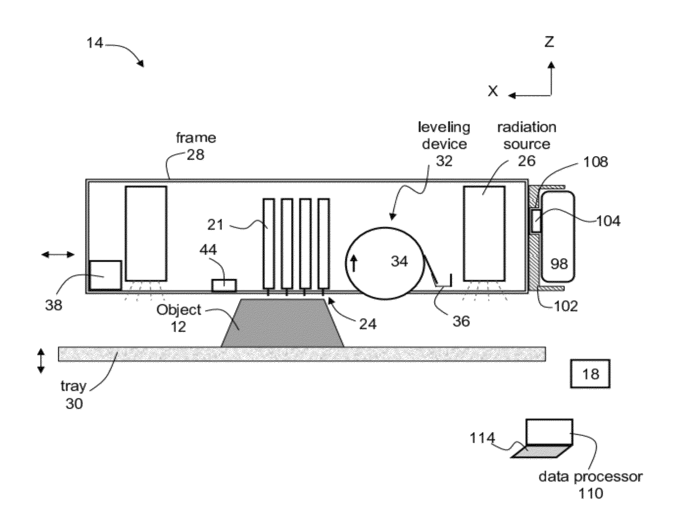
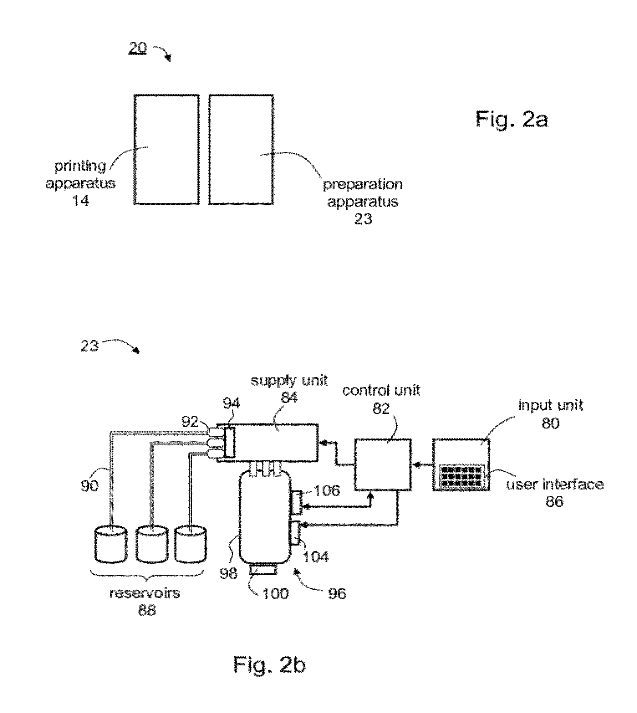
[0181](a) Reduce on-site stock and storage by enabling the use of a single modeling material to obtain different colors and / or different properties.[0182](b) Increase material shelf life:[0183](i) An additive, e.g., a curing agent, a hardening agent, a dye or pigment (color mix), might have a generally negative effect on the shelf life of the modeling material. By enabling the user to introduce the additive to the modeling material on site, per use and shortly before use, will enable the user to benefit from the full shelf life of the product.[0184](ii) The additive being required in relatively small amounts could be refrigerated or otherwise stored under optimal conditions to further increase its shelf life.

Materials

[0185]A cartridge containing modeling material.

[0186]A set of syringes containing different additives, e.g., dye solutions or pigment dispersions or combinations between dyes and pigments. The syringes may be external or internal to the apparatus; and may be i...

example 2

Motivation

[0193](a) Dual curing: Specially designed formulations containing dual curing components cannot be prepared by the resin manufacturer due to a short pot life. Once the components have been mixed, the pot life of some of such specially designed formulations may, in some cases, last only a few days, after which time, the product partially polymerizes, altering its properties to the extent that it is no longer appropriate for its intended use.[0194](b) Example: hydroxyl reaction with isocyanate in addition to radical polymerization of acrylic double bonds.

Materials

[0195]A cartridge containing modeling material.

[0196]A syringe containing isocyanate component.

Method

[0197](a) Inject isocyanate[0198](b) Cartridge agitation: mixing of base modeling materials and isocyanate.[0199](c) Allow bubbles to dissipate.[0200](d) Load cartridge to machine[0201](e) Carry out material resin replacement if necessary[0202](f) Build desired parts[0203](g) Flush out system in order to remove react...

example 3

Motivation

[0205]Thiolene reaction: This reaction, while having many advantages, suffers from very short formulation shelf life.

Materials

[0206]A cartridge containing a metha / acryl modeling material.

[0207]A syringe containing mercaptopropionate component.

Method

[0208](a) Inject mercaptopropionate.[0209](b) Cartridge agitation: mixing of base modeling materials and mercaptopropionate.[0210](c) Allow bubbles to dissipate.[0211](d) Load cartridge to machine[0212](e) Carry out material resin replacement if necessary[0213](f) Material ready for building.

[0214]Other chemicals can also be mixed using this technique. For example, a formulation can be stable until the addition of a catalyst, a cross linker, etc.

[0215]It is appreciated that certain features of the invention, which are, for clarity, described in the context of separate embodiments, may also be provided in combination in a single embodiment. Conversely, various features of the invention, which are, for brevity, described in the co...


PUM

PropertyMeasurementUnit
temperatureaaaaaaaaaa

Abstract

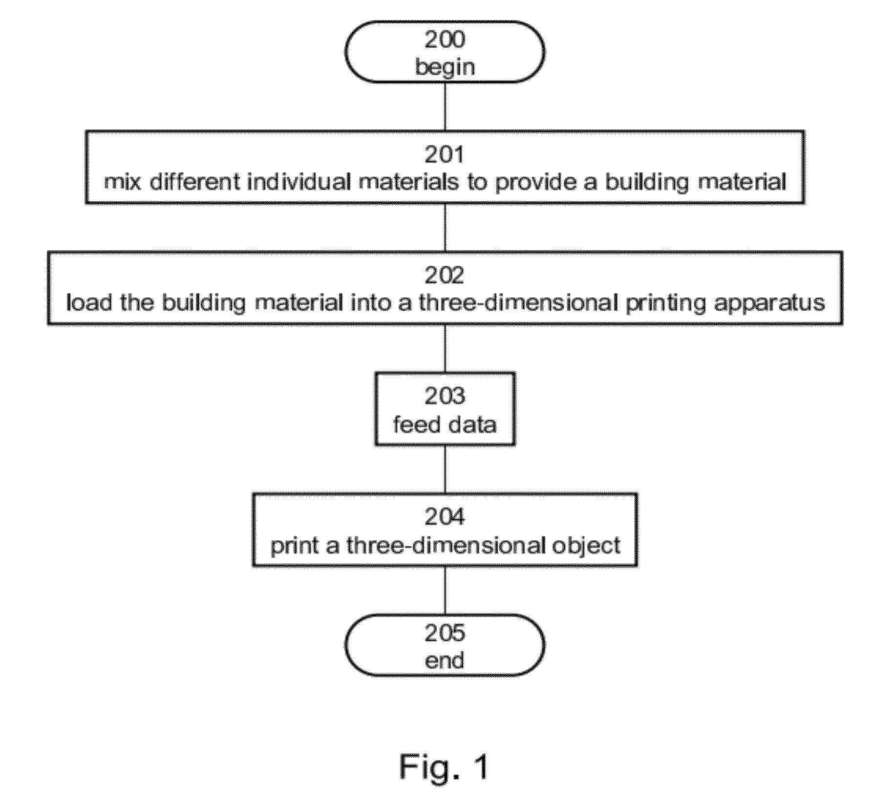
A method suitable for solid freeform fabrication is disclosed. The method comprises mixing respective amounts of a plurality of materials such as to provide a building material characterized by at least one attribute, and using the building material for fabricating a three-dimensional object.

Description

RELATED APPLICATION[0001]This application is a divisional of U.S. patent application Ser. No. 12 / 327,857 filed on Dec. 4, 2008, the contents of which are incorporated by reference as if fully set forth herein.FIELD AND BACKGROUND OF THE INVENTION[0002]The present invention relates to solid freeform fabrication (SFF) and, more particularly, to apparatus, system and method for the preparation of building material for solid freeform fabrication.[0003]Solid freeform fabrication processes are defined as processes in which objects are constructed in layers utilizing a computer model of the objects. The layers are deposited or formed by a suitable device which receives signals from a computer using, e.g., a computer aided design (CAD) software.[0004]Solid freeform fabrication is typically used in design-related fields where it is used for visualization, demonstration and mechanical prototyping. Thus, solid freeform fabrication facilitates rapid fabrication of functioning prototypes with mi...

Claims


Application Information

Patent Timeline
Patent Type & Authority Applications(United States)
IPC IPC(8): B29C49/78
CPCB29C67/0085B29C64/112B29C64/386B29C48/17B29C48/21B29C48/16B29C64/314B29C64/343B33Y30/00B33Y70/00B33Y70/10B33Y50/02B29C35/08B29C49/78
Inventor NAPADENSKY, EDUARDO
Owner STRATASYS LTD
Learn More