
Implant system

Active Publication Date: 2012-11-01
SKULLE IMPLANTS
View PDF2 Cites 7 Cited by
  • Summary
  • Abstract
  • Description
  • Claims
  • Application Information

AI Technical Summary

Benefits of technology

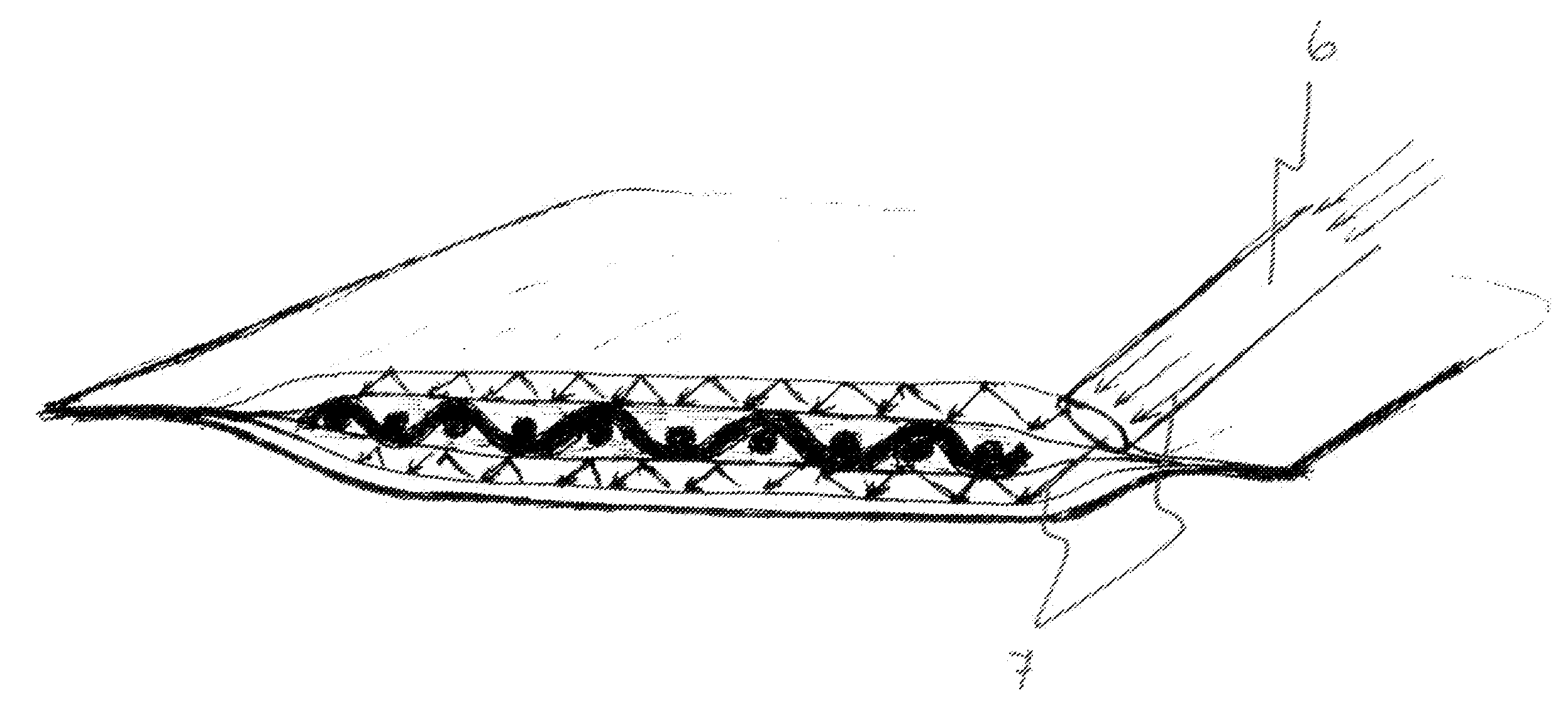
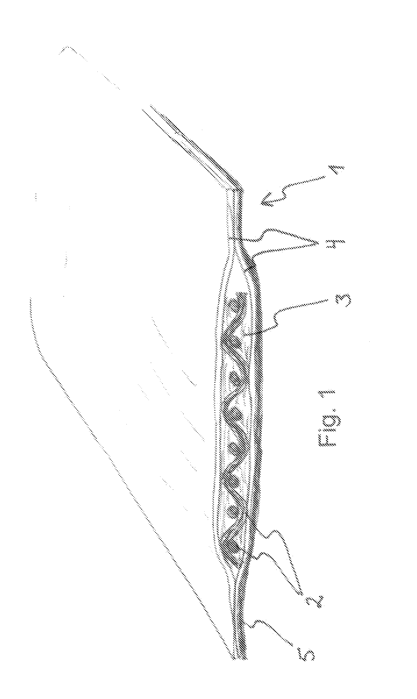
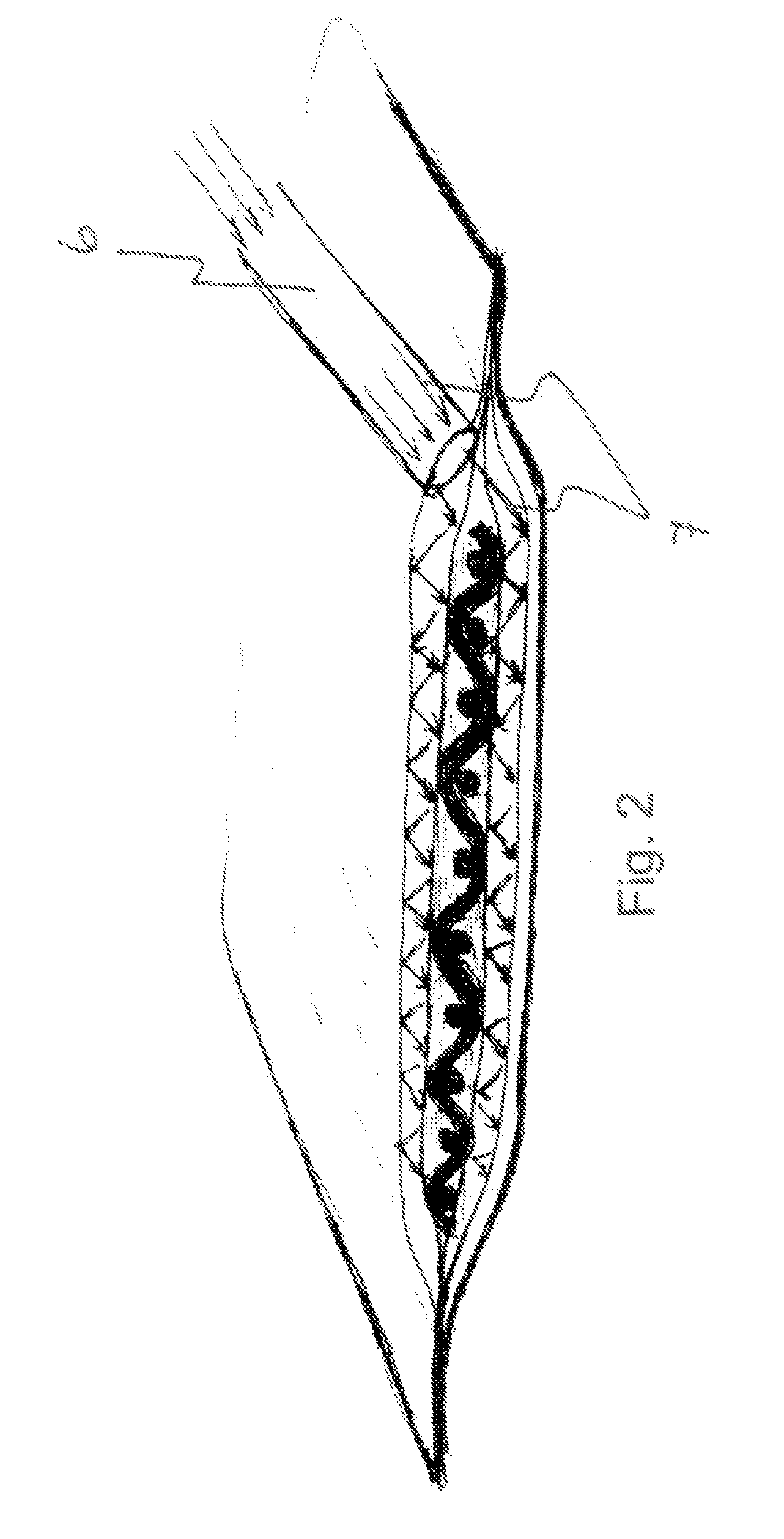
[0005]An object of the present invention is to provide an implant system where it would be safe to correctly shape the implant material to the required, sometimes quite complicated shape and then to be able to cure the implant material to this exact shape.
[0006]Another object of the invention is to provide an implant system where the risks of contamination of the patient can be minimised, i.a. by avoiding contact between the surgeon and the implant material and between the possibly irritating components of the uncured implant material and the patient.
[0007]A yet further object of the invention is to provide an implant system where the finished implant has improved adhesion to the surrounding tissues.

Problems solved by technology

Typical problems in this field are the shaping of the implant material, as this is usually made by hands by the surgeon, which includes a risk of contamination of the implant material.

Method used


Image

  • Implant system
  • Implant system
  • Implant system

Examples


example 1

[0053]An implant system for long bone fixation plate to be polymerised in situ was made as follows: non-cured implant prepreg material (i.e. implantable material) in the average form and size of a long bone fracture fixation plate (18 mm in length, 14 mm in width and 3 mm in thickness) was placed to a vacuum package of polyethylene sheets thus forming an inner part of the casing. The vacuum package with the implant prepreg therein was placed to an environmental light protecting package (i.e. an outer part of the casing) having an opening in one end of the package for the light emission tip of a photopolymerization device. The environmental light protecting package was made of aluminium having a thickness of 0.05 mm.

[0054]These two packages were then placed into a covering package after which the implant prepreg and the packages were sterilized. During the surgical procedure, the covering package of the implant was removed and the implant with the environmental light protecting packa...

example 2

[0057]An implant system for long bone fixation plate to be formed in situ and polymerised with a light curing device at the operation theatre was made as follows: the non-cured implant prepreg material of a polymeric-based composite of bis-GMA resin system and S-glass (high strength glass) fibers containing a titanium mesh of 0.1 mm in thickness for providing adequate radio-opacity and supporting the metal foil to retain the shape is used in the average form and size of long bone fracture fixation plate (18 mm in length, 14 mm in width and 3 mm in thickness) was placed to the vacuum package of polyethylene sheets. The vacuum package had, as an integral part, a metal foil as one surface of the package enabling bending and forming of the prepreg to correspond to the bone. The package remains the form by permanent deformation of the metal foil and the prepreg can be placed in its anatomical form to the light curing device and be polymerised. The casing is thus formed from a combination...

example 3

[0059]An implant system was prepared, with polymerised particulate filler or metal fixation cylinders within the prepreg. The fixation cylinders were attached by mechanical retentions to the fibre structure of the composite implant prepreg. Before polymerisation of the prepreg, the fixation cylinders could be moved and angulated inside the package by sliding the cylinders in the prepreg material. During polymerisation, the fixation cylinders were attached to the prepreg and were used in fixation of the implant by screws.


PUM


Abstract

The present invention relates to an implant system comprising implantable material in at least partially uncured form, contained in a closed casing, under vacuum and sterilised, and a closed bag containing the casing. The system is characterised in that at least 5% of the surface of the casing comprises sheet-like material having a thickness of 0.05-5 mm and having an original form, the sheet-like material being selected from the group consisting of metallic materials, polymers, bioceramic materials and composites thereof, provided that the material, once deformed from its original form to a changed form, is capable of maintaining that changed form unless subjected to external forces.

Description

FIELD OF THE INVENTION[0001]The present invention relates to an implant system comprising implantable material in at least partially uncured form and contained in a closed casing under vacuum and sterilised as well as a closed bag containing the casing. The invention also relates to an implant obtainable from said implant system as well as to a method for manufacturing an implant.BACKGROUND OF THE INVENTION[0002]Various implant materials are known in the art and are widely used. Some promising implant materials, especially for bone implant for correcting defects in bones, are different composites comprising bioactive glass and hydroxyapatite. Typically, these materials are mouldable and soft before they are cured to form a solid piece used as an implant. Typical problems in this field are the shaping of the implant material, as this is usually made by hands by the surgeon, which includes a risk of contamination of the implant material.[0003]Document WO 2008 / 079861 discloses an impla...

Claims


Application Information

Patent Timeline
IPC IPC(8): A61B17/68A61B17/00
CPCA61L31/14A61L27/50
Inventor VALLITTU, PEKKA
Owner SKULLE IMPLANTS
Learn More