Instrument for positioning an intervertebral implant for the fusion between two vertebral bodies of a vertebral column

Active Publication Date: 2012-11-01
MEDACTA INT SA
View PDF7 Cites 31 Cited by
  • Summary
  • Abstract
  • Description
  • Claims
  • Application Information

AI Technical Summary

Benefits of technology

[0017]A sleeve may be incorporated inside the handle with a distal end projection from the handle, the shaft being rotatable mounted on the distal end of the sleeve through a thumb wheel. The clamps of the grasping head may comprise internal teeth for improving the gripping action. The stem may be extended through the sleeve up to the proximal end of the h

Problems solved by technology

This approach has a complex instrument locking mechanism instead of a 90° lock/unlock mechanism and it may be impossible to engage the instrument in-situ.
The implant fixation is done with a linear movement of the sleeve, but this linear movement can cause tissue damage and it is not as simple as a 90° locking.
It may be difficult to engage the instrument is-situ.
The engagement/disengagement mechanism may be complex and uncomfortable.
The interface is a f

Method used


Image

  • Instrument for positioning an intervertebral implant for the fusion between two vertebral bodies of a vertebral column
  • Instrument for positioning an intervertebral implant for the fusion between two vertebral bodies of a vertebral column
  • Instrument for positioning an intervertebral implant for the fusion between two vertebral bodies of a vertebral column

Examples


Embodiment Construction

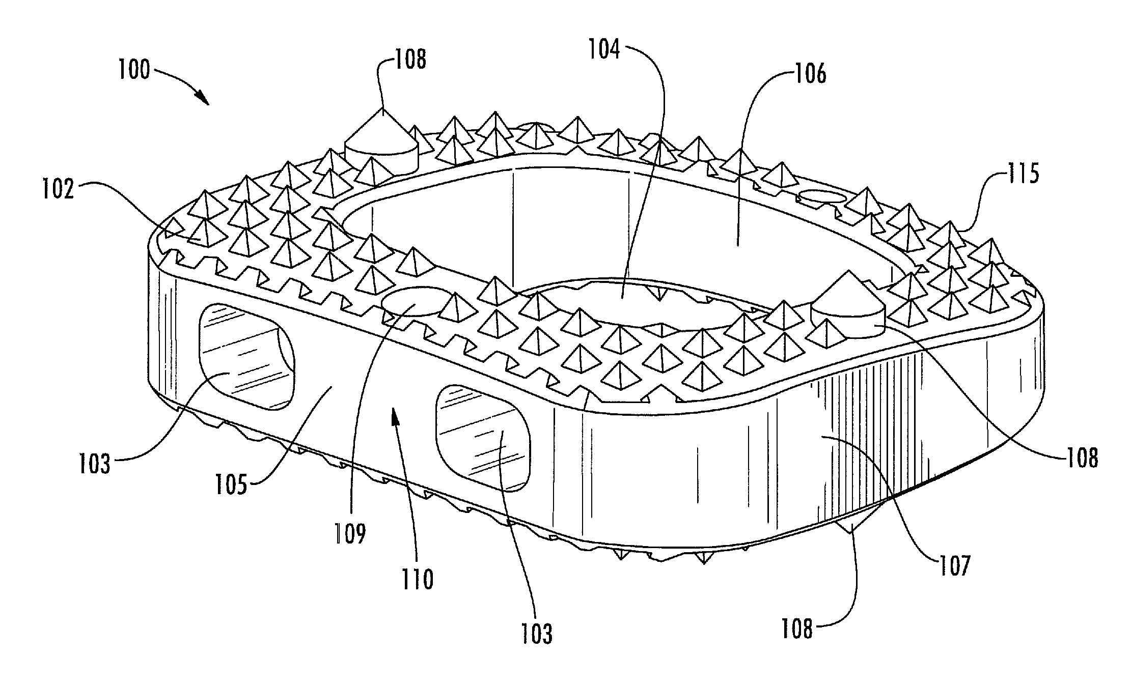
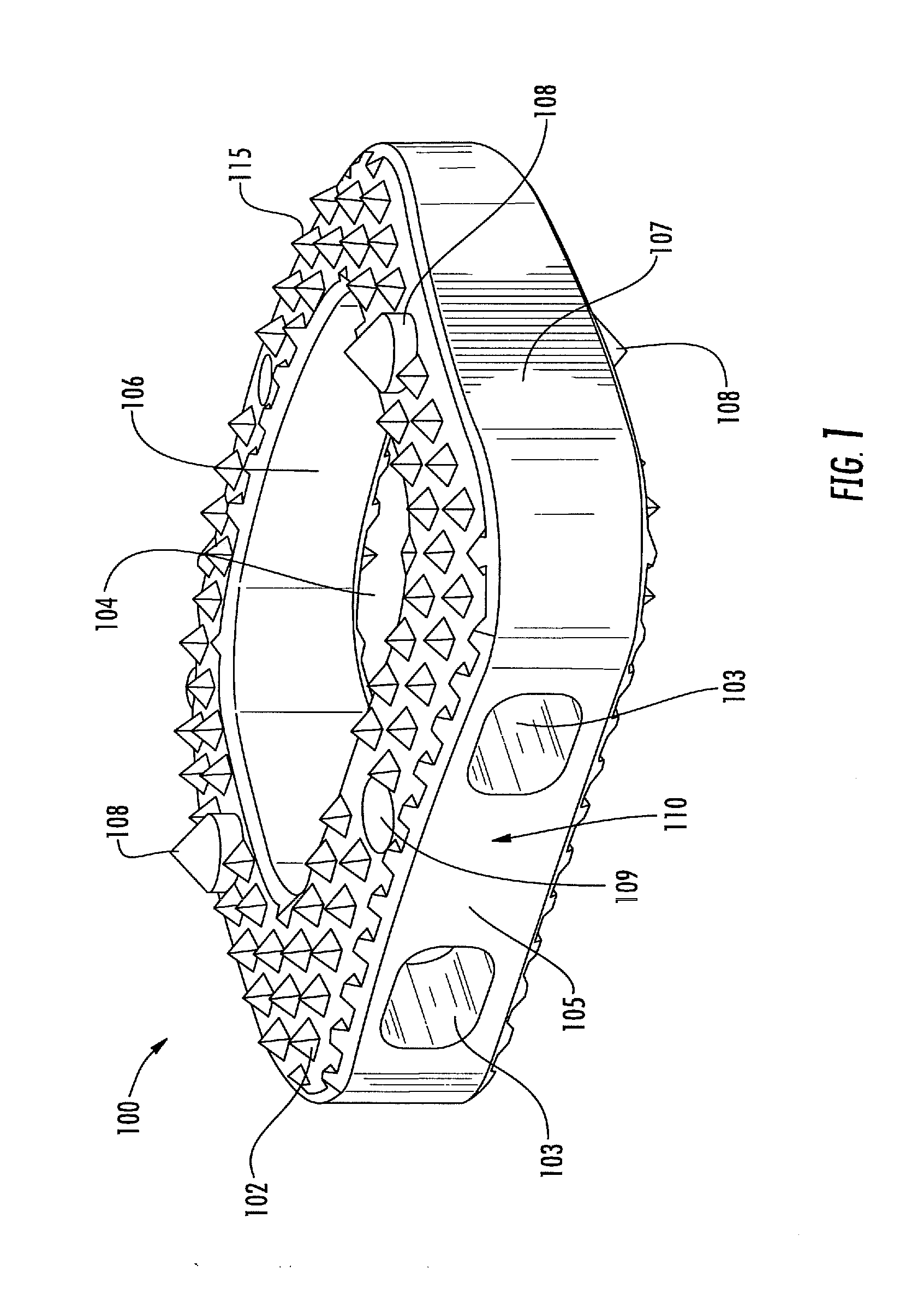
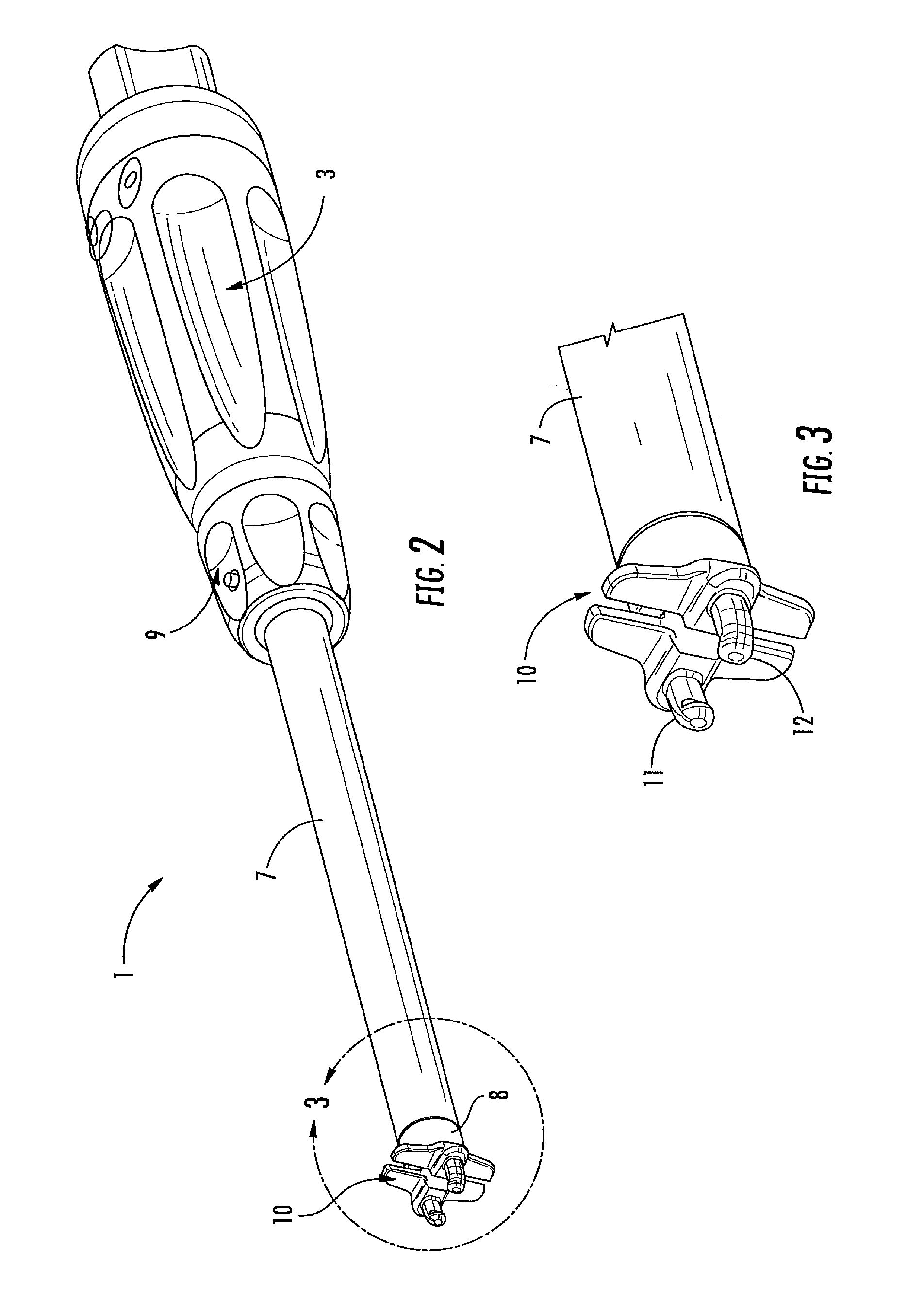
[0047]With reference to the drawing figures, 100 is globally shown as an intervertebral implant to be positioned with the instrument 1 of the present invention for permitting the fusion between two vertebral bodies of a vertebral column. With reference to FIG. 1, the structure of the implant 100 is disclosed to allow a better understanding of its use and how the instrument 1 is suitable to grip such an implant 100 or other implants of similar use.

[0048]The implant 100 has been specifically realized for allowing vertebral operations according to the requirement of the modern Minimally Invasive Surgery. The implant 100 is mainly dedicated to the use in cervical intervertebral surgery, however, nothing prevents that it may be adopted in other surgery techniques, such as PLIF or ALIF.

[0049]The implant 100 has a main body 102 realized with a biocompatible radiolucent synthetic material, for example, a Polyetheretherketone (PEEK) structure having a favorable modulus of elasticity. The bod...


PUM


Abstract

An instrument positions an intervertebral implant for the fusion between two vertebral bodies of a vertebral column. The instrument may include a handle having a proximal and a distal end, a locking shaft extended from the distal end of the handle, and a grasping head at the distal end of the shaft. The locking shaft may be cannulated, and a stem may be hosted inside the cannulated shaft passing through the handle. The stem may be free to rotate with respect to the locking shaft, or vice versa, while the grasping head may be formed at the distal end of the stem with a couple of prongs or clamps toward the other according to an angular relative rotation of the stem with respect to the locking shaft. The instrument may allow the surgeon to grip a corresponding implant with a simple rotation movement of his hand.

Description

FIELD OF THE INVENTION[0001]The present invention relates to an instrument for positioning an intervertebral implant for fusion between vertebral bodies of a vertebral column.BACKGROUND OF THE INVENTION[0002]A known approach is disclosed in U.S. Pat. No. 6,159,215, which discloses a method for delivering a vertebral body spacer to the disc space. The instrument has two fingers, which are movable relative to one another and adapted to grip the spacer when the shaft is moved to actuate the fingers. The handle portion includes a grip and a trigger toward the grip for causing the fingers to move toward one another. The fixation is done by way of an extensive linear movement.[0003]Another approach is described in U.S. Patent Application Publication No. 2006 / 0235426, which discloses an implant, an instrument, and a method for positioning a spinal implant in a spinal disc space between adjacent vertebrae. That implant is fixed by a hinged forceps tip. The forceps tip can be angularly adjus...

Claims


Application Information

Patent Timeline
IPC IPC(8): A61B17/88
CPCA61F2/4465A61F2/447A61F2/4611A61F2002/30785A61F2002/4629A61F2002/30841A61F2002/4475A61F2002/4622A61F2002/4623A61F2002/3082A61F2/4603A61F2002/30593
Inventor SICCARDI, FRANCESCOFIECHTER, MEINRADJESZENSZKY, DEZSOFEKETE, ZSOLTHEYDE, CHRISTOPH E.
Owner MEDACTA INT SA
Why Eureka
Try Eureka