Biodegradable Drug Eluting stent Pattern

a stent pattern and biodegradable technology, applied in the field of radially expandable polymeric endoprostheses, can solve the problems of stent struts or bar arms cracking during crimping, localized portions of the stent pattern subjected to substantial deformation tend to be the most vulnerable to failure, and insufficient radial strength

Inactive Publication Date: 2012-11-01
WU TIM
View PDF5 Cites 32 Cited by
  • Summary
  • Abstract
  • Description
  • Claims
  • Application Information

AI Technical Summary

Benefits of technology

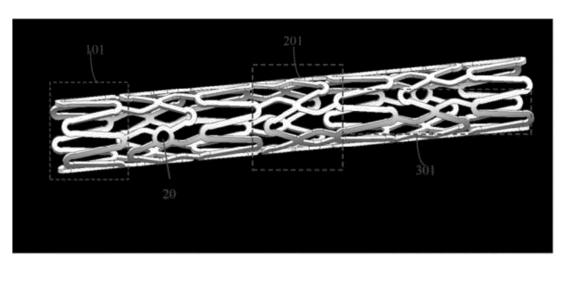
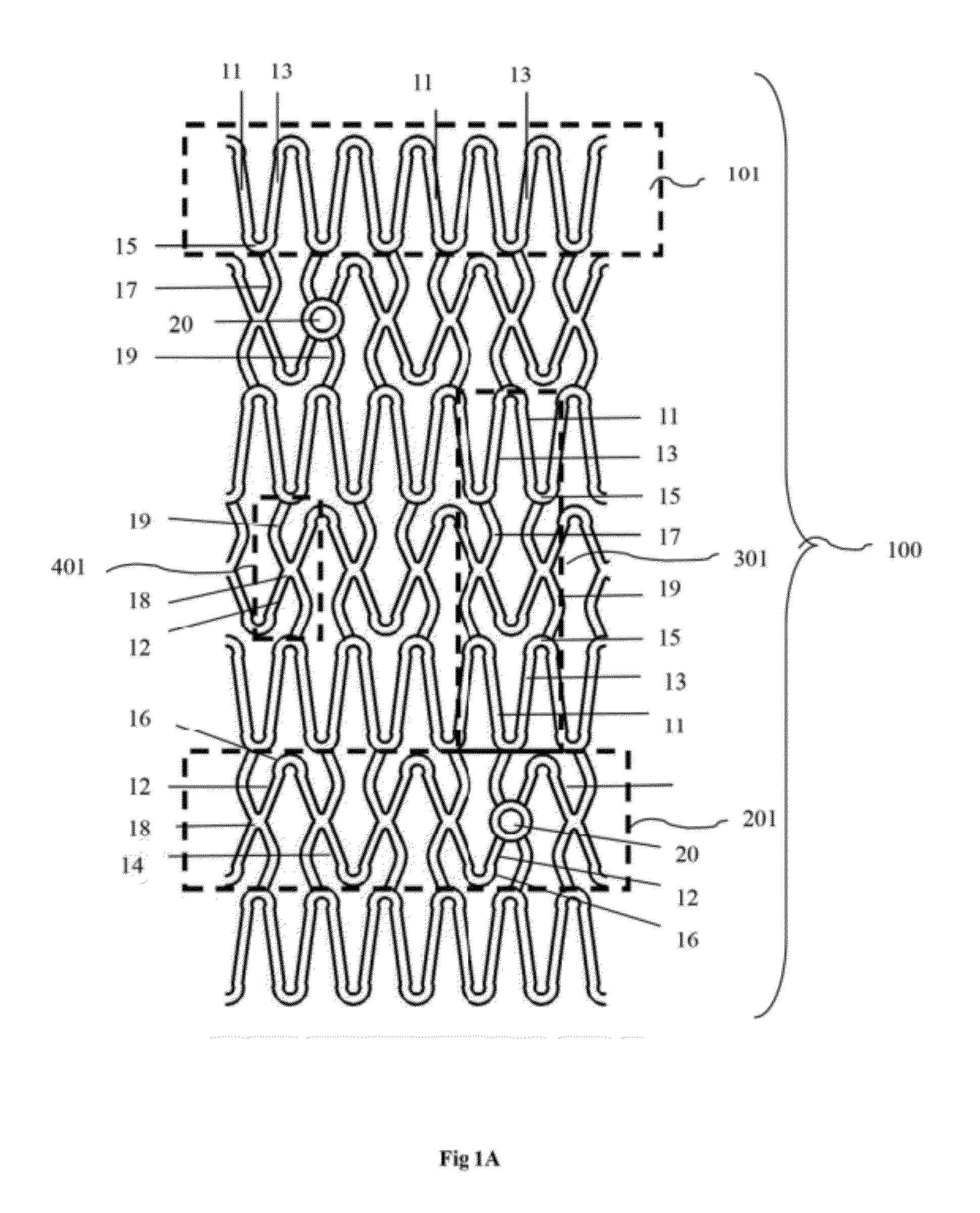
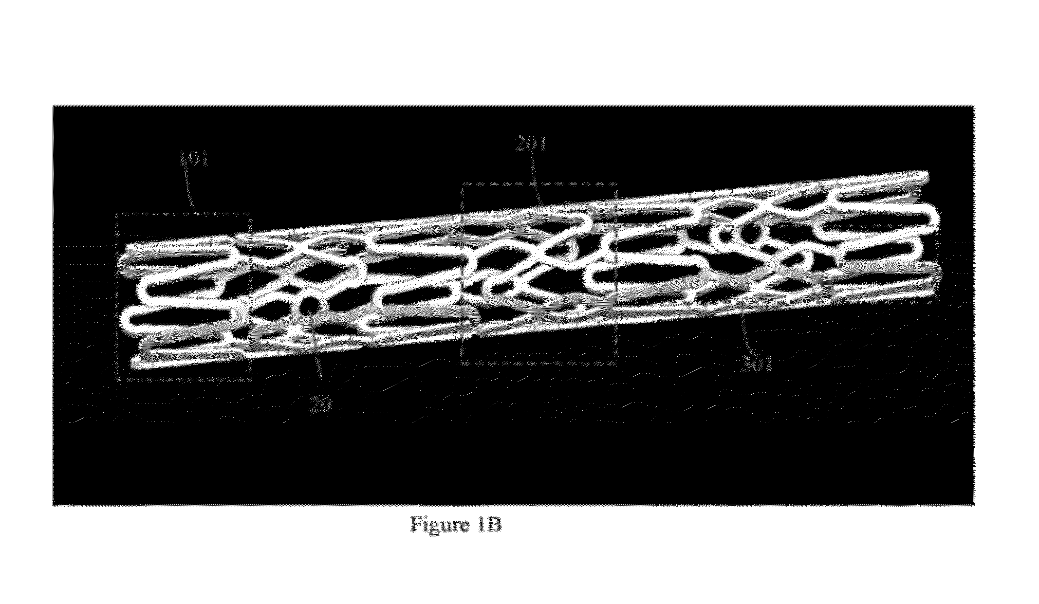
[0016]The present inventors have proposed novel designs which may employ such bioabsorbable, biocompatible and biodegradable material to make advantageous scaffolds, which may afford a flexibility and stretchability very suitable for implantation in the pulsatile movements, contractions and relaxations of, for example, the cardiovascular system.

Problems solved by technology

Inadequate radial strength potentially contributes to a relatively high incidence of recoil of polymeric stents after implantation into vessels.
Another potential problem with polymeric steals is that their struts or bar arms can crack during crimping and expansion, especially for brittle polymers.
The localized portions of the stent pattern subjected to substantial deformation tend to be the most vulnerable to failure.
Furthermore, in order to have adequate mechanical strength, polymeric stems may require significantly thicker struts than a metallic stent, which results in an undesirably larger profile.
Another potential problem with polymeric stents is long term creep.
Long term creep occurs even when the applied load is constant.
Long term creep in a polymeric stent reduces the effectiveness of a stent in maintaining a desired vascular patency.

Method used


Image

  • Biodegradable Drug Eluting stent Pattern
  • Biodegradable Drug Eluting stent Pattern
  • Biodegradable Drug Eluting stent Pattern

Examples


examples

[0123]An embodiment of the present invention is illustrated by the following set forth example. All parameters and data are not to be construed to unduly limit the scope of the embodiments of the invention.

[0124]FIG. 7 depicts an invented biodegradable stent crimped on a balloon catheter. As depicted in the figure, the crimped biodegradable stent has a minimum acceptable profile.

[0125]FIG. 8 depicts the biodegradable stent in an expanded condition. As depicted in the figure, metal makers were located inside the strut.

[0126]FIG. 9 depicts an angiography of described biodegradable stent in pig coronary artery at implantation. As depicted in figure, the biodegradable stent is radiolucent, but radiopaque marker is clearly identified.

[0127]FIG. 10 depicts the pathological images of invented biodegradable stent at one month post implantation in pig coronary artery. As depicted, there are no any indication of stent recoil, restenosis formation and arterial tissue inflammation at one month ...


PUM

PropertyMeasurementUnit
diameteraaaaaaaaaa
diameteraaaaaaaaaa
diameteraaaaaaaaaa

Abstract

In embodiment, pattern for polymeric radially expandable implantable medical devices such as stents for implantation into a bodily lumen are disclosed.

Description

CROSS-REFERENCE TO RELATED APPLICATIONS[0001]This application claims the benefit of the U.S. provisional application No. 61,488,748, filed on May 22, 2011. This application is also a continuation-in-part of the U.S. patent application Ser. No. 11 / 843,528, filed on Aug. 22, 2007, which claims the benefit of U.S. provisional patent application No. 60 / 823,168, filed on Aug. 22, 2006. This application is also a continuation-in-part of the U.S. patent application Ser. No. 12 / 209,104, filed on Sep. 11, 2008, which claims the benefit of U.S. provisional patent application No. 60 / 578,219, filed on Jun. 8, 2004. This application also claims the benefit of the U.S. provisional application No. 61 / 368,833, filed on Jul. 29, 2010 and U.S. provisional patent application No. 61 / 427,141 filed on Dec. 24, 2010. The disclosures of all of which are hereby incorporated by reference in their entireties.FIELD OF THE INVENTION[0002]The invention relates to radially expandable polymeric endoprostheses for ...

Claims


Application Information

Patent Timeline
Patent Type & Authority Applications(United States)
IPC IPC(8): A61F2/82A61F2/84
CPCA61B17/06166A61F2230/0054A61B2017/00004A61F2/28A61F2/30767A61F2/3094A61F2/915A61F2002/30062A61F2002/30064A61F2002/30677A61F2002/91525A61F2002/91558A61F2002/91575A61F2002/91583A61F2210/0004A61F2250/0067A61F2250/0098A61F2310/00011A61F2310/00293A61F2310/0097A61L27/46A61L27/58A61L31/127A61L31/148A61B17/86C08L67/04
Inventor WU, TIM
Owner WU TIM
Why Eureka
Try Eureka