Artificial heart valve

Active Publication Date: 2019-12-26
SHANGHAI JOY MEDICAL DEVICES CO LTD
View PDF0 Cites 3 Cited by
  • Summary
  • Abstract
  • Description
  • Claims
  • Application Information

AI Technical Summary

Benefits of technology

[0044]Compared with the prior art, the prosthetic valve of the present disclo

Problems solved by technology

However, the patches that are used in the above surgical treatments cannot conform to growth of the human body, and easily generate restenosis or valve lesions, and the condition will be increasingly severe with age.
In the last few decades, along with the developments in heart surgery, increasing numbers of patients having complex congenital heart diseases have lived through childhood and survived to adolescence or adulthood, and thus regurgitation of the pulmonary artery has become an increasingly problematic common disease.
Transcatheter valve implant only serves as remedy for pulmonary regurgitation from the surgery and requires a secondary procedure, and the balloon expansion may also result in the complication of pulmonary regurgitation.
In addition, because the patients of congenital heart diseases are mostly infants and youngsters, prosthetic valves cannot adapt for the growth of the patients, and thus have limited functionality.
Surgery has a remarkable curative effect for treating the patients that undergo RVOT surgery for the first time, but surgery for the second time increases risks of dissociation, hemorrhage and hemostasis, and complications.
That is because, although the existing valves can secure themselves to the blood vessel inner wall by the radial supporting force of the stent, most of the positions to secure the stent have undergone surgical treatment, such as the valve annulus was

Method used


Image

  • Artificial heart valve
  • Artificial heart valve
  • Artificial heart valve

Examples


embodiment 1

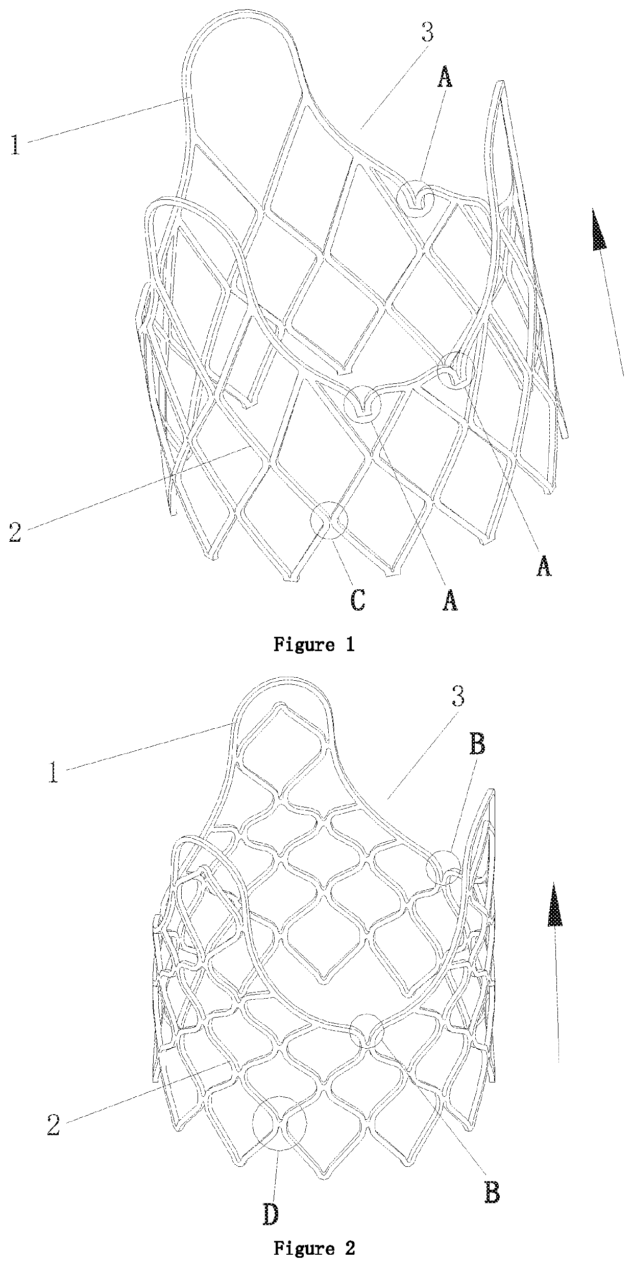
[0061]FIG. 1 shows one of the embodiments of the present disclosure. In the present embodiment, the prosthetic valve that is intended for the pulmonary and tricuspid implant comprises a tubular frame 2. The frame 2 is of a lattice structure, and can be radially expanded and deformed. Three U-shaped protrusions 1 on the frame 2 are evenly arranged at the downstream end relative to blood stream direction. U-shaped recession 3 is provided between every two adjacent protrusions 1. Several foldable joints are provided on each edge of the recessions 3, such as the foldable joints A shown in FIG. 1. The protrusions 1 and the recessions 3 are stretched when the prosthetic valve is expanded during implant, and the foldable joints A are unfolded when the prosthetic valve is further expanded after implant.

[0062]The blood stream direction is indicated by the arrow in FIG. 1. The numbers of the protrusions 1 and the recessions 3 are preferably three, and the numbers may be increased according to...

embodiment 2

[0086]FIG. 2 shows Embodiment 2 of the present disclosure. In the present embodiment, what is different from Embodiment 1 is that all of the protrusions 1 and the recessions 3 are U- shaped, the recessions 3 comprise a combination of two smooth arcuate edges, the two arcuate edges are individually part of the protrusions 1 adjacent to the recessions, and the joint end of the two arcuate edges are connected to the lattice structure of the frame 2.

[0087]In the present embodiment, 1-3 foldable joints B are provided wherein at least 1 foldable joint 8 is provided between the bottom ends of the two smooth arcuate edges. When the prosthetic valve is expanded during implant, the foldable joints B are still in the folded state, and the foldable joints B are unfolded when the prosthetic valve is expanded after implant.

[0088]When the prosthetic valve is expanded after implant, the foldable joints B cannot be unfolded to be a smooth curve, but the foldable joints B have more integrated structu...

embodiment 3

[0092]FIG. 11 shows Embodiment 3 of the present disclosure. In this embodiment, what is different from Embodiment 1 is that U-shaped reinforcement 8 is connected to two edges of the corresponding recession 3, the protruding direction of the reinforcements 8 is the same as the direction of the protrusions 1, and the two bottom ends of the reinforcement 8 are respectively connected to the two edges of the corresponding recession 3.

[0093]Annular guide 7 is provided on the protruding portion of each reinforcement 8, and the annular guide 7 is formed by the bending edge at the protruding portion of the reinforcement.

[0094]The annular guide 7 may be connected to the retrieving element that is used in the implantation procedure in order to adjust the implantation position of the prosthetic valve.

[0095]The frame 2, the three U-shaped protrusions 1 and the reinforcements 8 are manufactured in one process. The reinforcements 8 may also be V-shaped.

[0096]The other parts of the prosthetic valve...


PUM


Abstract

A device for treating regurgitation of a tricuspid valve (4). The device comprises a tricuspid valve plug (21) capable of compressing and expanding and a tricuspid valve plug fixing device used for anchoring the tricuspid valve plug (21) to an orifice of the tricuspid valve (4). The tricuspid valve plug (21) is provided with an inflow end (42, 52) and an opposite outflow end (47, 57), and a prosthetic valve (50, 70) capable of being opened and closed is disposed in the tricuspid valve plug (21). When the tricuspid valve (4) is closed, the prosthetic valve (50, 70) is automatically closed, and when the tricuspid valve (4) is opened, the prosthetic valve (50, 70) is automatically opened. The device for treating regurgitation of a tricuspid valve (4) and the implantation method therefor help to treat regurgitation of a tricuspid valve and do not block the flow of blood in a heart, and the device can be recycled, has the characteristics of high operationality and high safety in minimally-invasive repair, and has high clinical value.

Description

CROSS REFERENCE TO RELATED APPLICATION[0001]This application is a national stage application of PCT / CN2017 / 079777, filed on Apr. 7, 2017. The international application is incorporated herein by reference in its entirety.TECHNICAL FIELD[0002]The present invention pertains to a prosthetic valve, which can be implanted into the pulmonary and / or tricuspid position in a human body to replace the diseased pulmonary or tricuspid valve.BACKGROUND OF THE INVENTION[0003]A human heart has four pumping chambers, that is, atrium sinistrum, atrium dextrum, ventriculus sinister and ventriculus dexter. The atriums receive blood from veins and pump it into the ventricles, and the ventricles discharge the blood to arteries. Atrium sinistrum, atrium dextrum, ventriculus sinister and ventriculus dexter individually have a valve, and the four valves control the blood stream that circulates through the human body. The mitral valve, located on the left part of heart, connects the atrium sinistrum with the...

Claims


Application Information

Patent Timeline
IPC IPC(8): A61F2/24
CPCB33Y80/00A61F2/2415A61F2210/0014A61F2/2418A61F2220/0008A61F2/91A61F2220/0075A61F2250/001A61F2250/0082A61F2/2412A61F2250/0048A61F2/915A61F2/2436A61F2002/9155
Inventor LEE, SHOUYANNAN, HONGXIA
Owner SHANGHAI JOY MEDICAL DEVICES CO LTD
Why Eureka
Try Eureka