Method for predicting modal damping ratio of composite head

a composite head and modal damping technology, applied in the field of modal damping ratio prediction of composite head, can solve the problems of difficult prediction of the ball hitting sound in the composite head, and the modal damping ratio of the composite head is difficult to predict, so as to achieve the effect of accurately predicting the modal damping ratio of the composite head

Active Publication Date: 2012-11-01
SUMITOMO RUBBER IND LTD
View PDF9 Cites 13 Cited by
  • Summary
  • Abstract
  • Description
  • Claims
  • Application Information

AI Technical Summary

Benefits of technology

[0024]The modal damping ratio of the com

Problems solved by technology

It is difficult to predict the ball hitting sound in the composite head.
One of th

Method used


Image

  • Method for predicting modal damping ratio of composite head
  • Method for predicting modal damping ratio of composite head
  • Method for predicting modal damping ratio of composite head

Examples


example 1

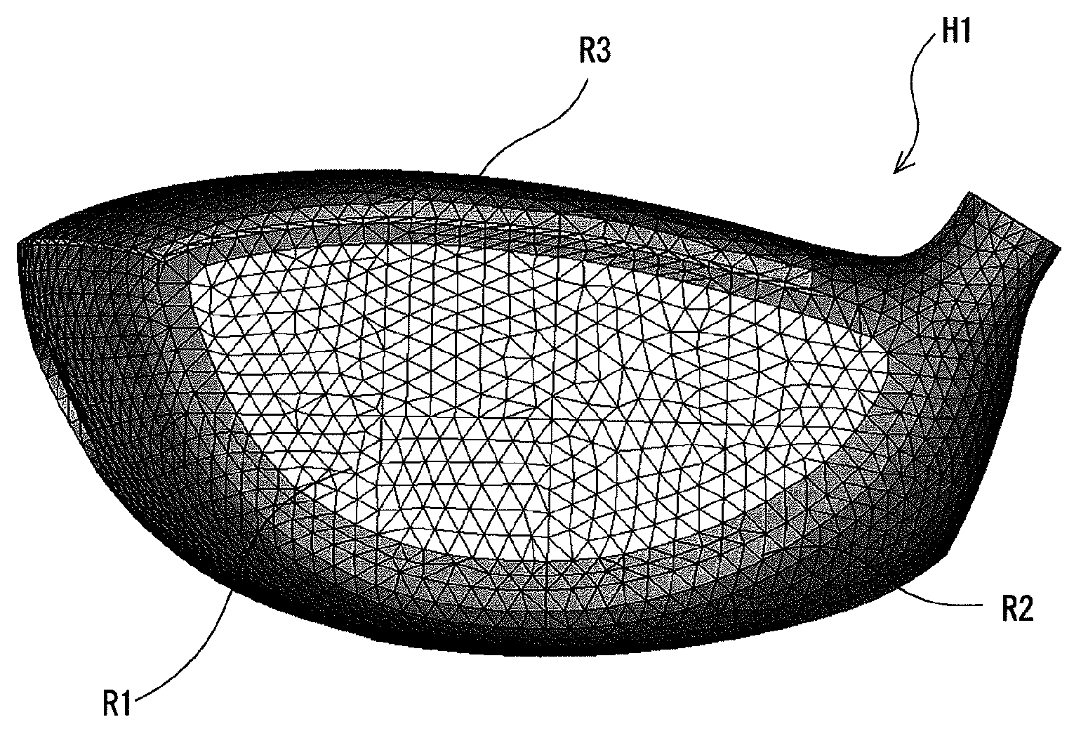
[0151]first region R1 (almost face)=material B (a titanium alloy is assumed; ζ=0.3)[0152]second region R2 (almost sole)=material C (a titanium alloy is assumed; ζ=0.3)[0153]third region R3 (almost crown)=material D (CFRP is assumed; ζ=1.5)

example 2

[0154]first region R1 (almost face)=material B (a titanium alloy is assumed; ζ=0.3)[0155]second region R2 (almost sole)=material C (a titanium alloy is assumed; ζ=0.3)[0156]third region R3 (almost crown)=material A (CFRP is assumed; ζ=0.3)

[0157]In example 2, the material damping ratio ζ is 0.3% in all the regions (regions R1, R2, and R3) of the head. Therefore, example 2 is similar to a head made of a single material. On the other hand, in example 1, the material damping ratio of the third region R3 (most of a crown part) is set to 1.5%, and the material damping ratios in the remaining regions R1 and R2 are set to 0.3%. Therefore, example 1 is similar to a composite head including a metal and CFRP.

[0158]FIG. 13 is a graph showing the modal damping ratios of examples 1 and 2. A thick line shows the modal damping ratio of example 1. A thin line shows the modal damping ratio of example 2. As shown in the graph, a mode (frequency) in which example 1 is close to example 2 exists. By cont...

reference example 1

[0160]The validity of a modal damping ratio to be calculated was examined using a calculation model of a flat plate shape comprising a single material. The shape of the flat plate was set to a rectangle. The flat plate had 201 mm long, 110 mm wide, and 2.48 mm thickness. A plate including only the material F was used as a calculation model. The damping ratio ζ of a material F was 1.5%, and the damping ratio ζ of the material was used as a representative value having no frequency dependency.

[0161]A modal damping ratio of the calculation model was calculated in the same manner as in example 1. A constraint condition was set to free. An acting point of a unit impact force was set to the center of the rectangle. The obtained modal damping ratio is shown in the graph of FIG. 14. An upper line graph of FIG. 14 shows the calculation result of reference example 1.


PUM


Abstract

A prediction method according to the present invention is a method for predicting a modal damping ratio of a composite head including two or more kinds of materials including a first material and a second material. The method includes the steps of: presuming at least a coefficient Px of a generalized Maxwell model M1 in the first material using a known material damping ratio ζ1; obtaining a calculation model of the head using the generalized Maxwell model M1; and calculating the modal damping ratio of the head based on analysis of the head using the calculation model. Preferably, the Maxwell model is further used also for the second material. Preferably, the method further includes the step of presuming a coefficient Py of a generalized Maxwell model M2 in the second material using a known material damping ratio ζ2.

Description

[0001]The present application claims priority on Patent Application No. 2011-100344 filed in JAPAN on Apr. 28, 2011, the entire contents of which are hereby incorporated by reference.BACKGROUND OF THE INVENTION[0002]1. Field of the Invention[0003]The present invention relates to a method for predicting a modal damping ratio of a composite head.[0004]2. Description of the Related Art[0005]A composite head has been known as a head including a plurality of materials. The compositing of the head advantageously enhances a degree of freedom of design. Particularly, a large-sized hollow head has a low degree of freedom of wall thickness distribution. For example, it is difficult to provide a center of gravity in a lower position in the large-sized hollow head. The composite head can solve the problem. The composite head is effective to provide the center of gravity in the lower position in the large-sized hollow head, for example.[0006]The typical example of the compositing is combination ...

Claims


Application Information

Patent Timeline
IPC IPC(8): G06F17/50G06F17/10A63B53/00A63B102/32
CPCG06F17/5009G06F17/5018G06F2217/16G06F17/10A63B53/047A63B53/04G06F17/50A63B71/081G06F2111/10G06F30/23G06F30/20A63B60/02G06F30/00G06F2113/26
Inventor HAYASE, SEIJIONUKI, MASAHIDE
Owner SUMITOMO RUBBER IND LTD
Why Eureka
Try Eureka