Radiographic imaging system and radiographic imaging method

a radiographic imaging and imaging system technology, applied in the field of radiographic imaging system and radiographic imaging method, can solve problems such as troublesome imaging process, complicated system configuration, and error in diagnosis, and achieve the effect of improving diagnosis precision, reducing error in relation to actual size, and correcting the shift in enlargement ratio

Inactive Publication Date: 2014-10-28
FUJIFILM CORP
View PDF33 Cites 14 Cited by
  • Summary
  • Abstract
  • Description
  • Claims
  • Application Information

AI Technical Summary

Benefits of technology

[0011]An object of the present invention is to solve the problems in the aforementioned prior art, and to provide a radiographic imaging system and a radiographic imaging method that can obtain an appropriate image even when a partition is tilted when imaging a subject with an upright position by the use of the partition.
[0014]It is preferred that further comprising a detector moving unit that causes the radiation detector to move in the length direction of the subject, wherein the image processor synthesizes a plurality of images, which are obtained by causing the radiation detector to move in the length direction of the subject through the use of the detector moving unit, irradiating the subject with radiation from the radiation source, and capturing the images of the subject divided in the length direction, and creates a long radiographic image.
[0021]According to the present invention, even when the partition is tilted when locating a subject at a predetermined position by the use of the partition and imaging the subject with an upright position, it is possible to correct a captured image based on the tilt. In addition, since the distance between the partition and the radiation source can be measured, there is no trapezoidal distortion or the like and the shift in enlargement ratio can be corrected, whereby it is possible to obtain an image of the subject having a small error in relation to the actual size. Accordingly, regarding a long radiographic image of the subject obtained by synthesizing plural images, there is no trapezoidal distortion and the error in relation to the actual size can be reduced. As a result, it is possible to improve diagnosis precision.
[0022]Since it is possible to correct a captured image based on the tilt of the partition, it is not necessary to adjust the position of the partition and to adjust the tilt of the partition. Accordingly, it is possible to facilitate the installation of the partition and to simplify the configuration of the partition.

Problems solved by technology

Accordingly, when a large difference is present between an actual size and an image size, an erroneous diagnosis may result.
However, in the radiographic imaging system detecting a blur of a subject like the X-ray imaging apparatus disclosed in JP 2004-0568 A, there is a problem in that the system configuration is complicated.
In addition, since it is necessary to detect the blur of a subject, there is also a problem in that imaging processes are troublesome.
In this way, in the radiographic imaging system in which a partition is disposed to image a long area, there is presently no way to raise the positional precision of the partition causing a patient to stand at a predetermined position and the upright stand.

Method used


Image

  • Radiographic imaging system and radiographic imaging method
  • Radiographic imaging system and radiographic imaging method
  • Radiographic imaging system and radiographic imaging method

Examples


first embodiment

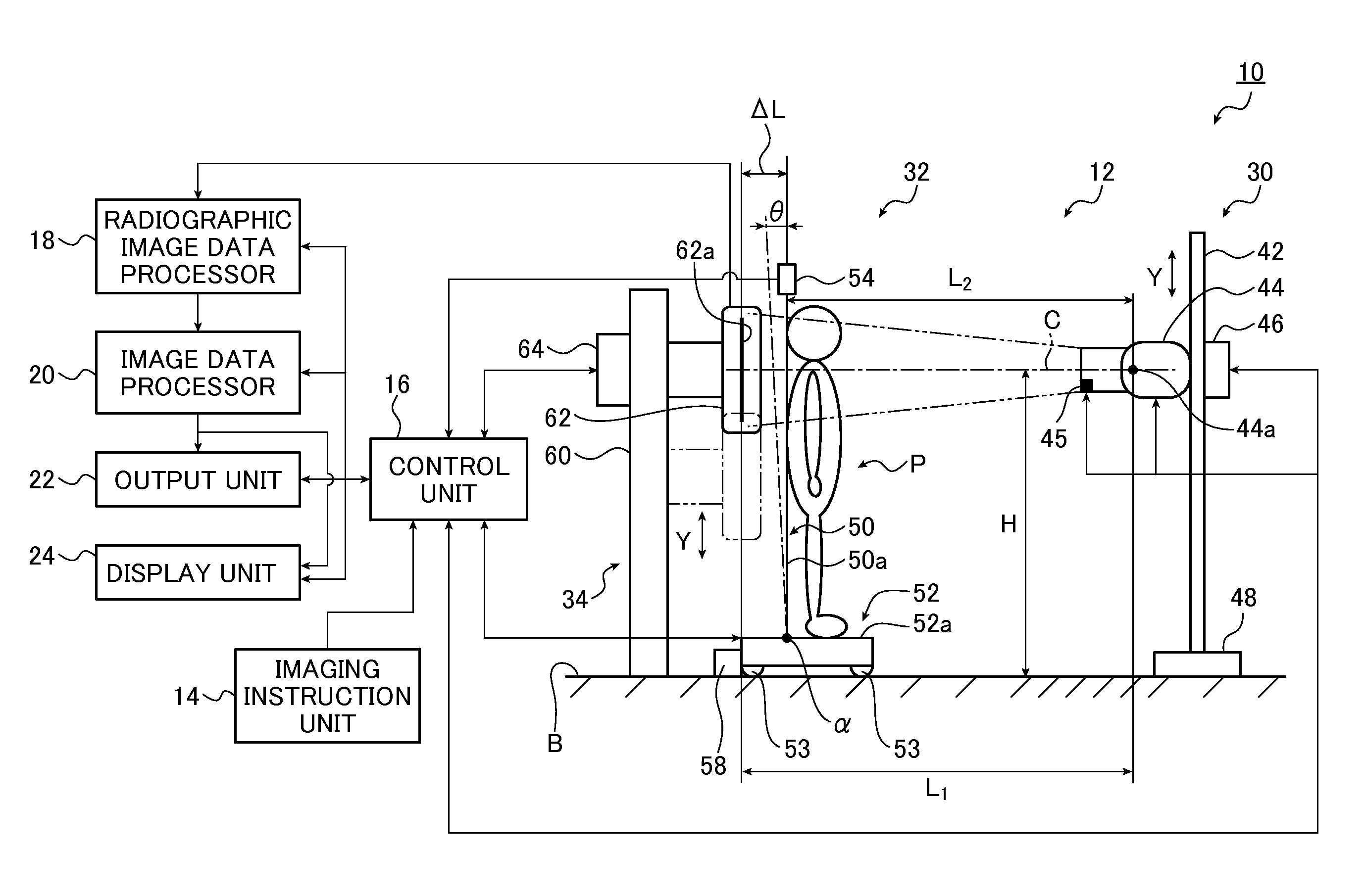
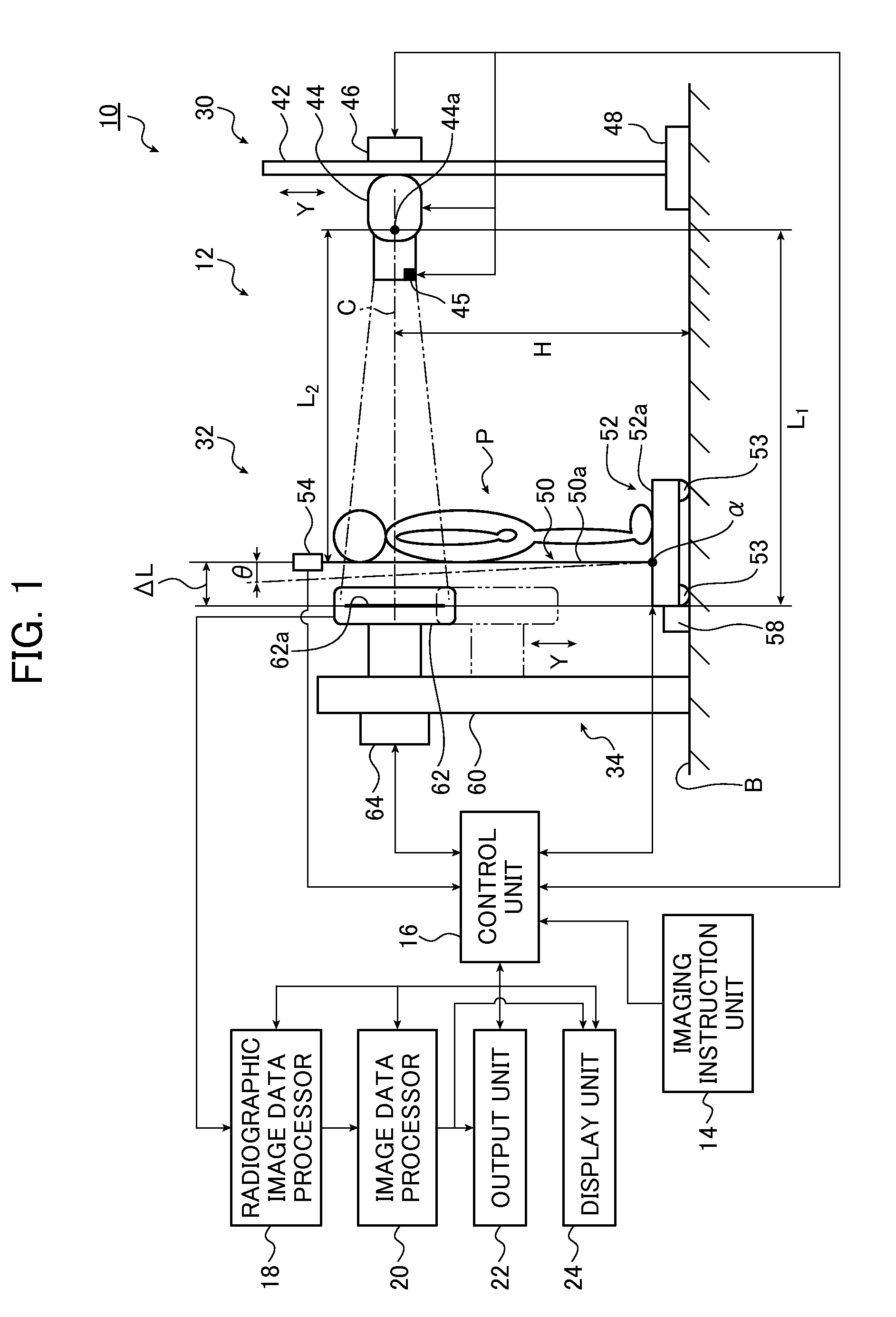
[0029]FIG. 1 is a schematic diagram illustrating a radiographic imaging system according to the present invention.

[0030]As shown in FIG. 1, a radiographic imaging system 10 (hereinafter, also referred to as an imaging system 10) includes an imaging unit 12, an imaging instruction unit 14, a control unit 16, a radiographic image data processor 18, an image data processor 20, an output unit 22, and a display unit 24.

[0031]The imaging instruction unit 14 sets an imaging menu, an imaging condition, an imaging mode, and the like and gives instructions for imaging a subject P. The imaging instruction unit 14 includes an input key (not shown) for setting an imaging menu, an imaging condition, and an imaging mode and an imaging instructor (not shown).

[0032]For example, a two-step push type imaging button is used as the imaging instructor. When the imaging button is pushed to a first step, for example, when the imaging button is half pushed, an imaging standby state is set. When the imaging ...

second embodiment

[0126]the invention will be described below.

[0127]FIG. 5 is a schematic diagram illustrating a radiographic imaging system according to a second embodiment of the invention.

[0128]In this embodiment, the same elements as the radiographic imaging system 10 according to the first embodiment shown in FIG. 1 are referenced by the same reference signs and the detailed description thereof will not be repeated.

[0129]A radiographic imaging system 10a (hereinafter, also referred to as an imaging system 10a) according to this embodiment shown in FIG. 5 is different from the radiographic imaging system 10 (see FIG. 1) according to the first embodiment in the configuration of the partition unit 32a and is equal to the radiographic imaging system 10 according to the first embodiment in the other configurations, the detailed description of which will not be repeated.

[0130]The partition unit 32a of the imaging system 10a according to this embodiment is different from the partition unit 32 of the fi...


PUM


Abstract

A radiographic imaging system is capturing a radiographic image of a subject. The radiographic imaging system has a radiation detector that detects radiation from which the radiographic image is obtained, a radiation source that irradiates the radiation detector with the radiation, a partition that is disposed adjacent to the radiation detector and that locates the subject at a predetermined position relative to the radiation detector, a distance measuring unit that measures a distance between the partition and the radiation source, a tilt detecting unit that measures a tilt of the partition, and an image processor that corrects the captured radiographic image based on the distance between the partition and the radiation source obtained by the distance measuring unit and the tilt of the partition obtained by the tilt detection unit.

Description

CROSS-REFERENCE TO RELATED APPLICATIONS[0001]The present application claims priority from Japanese Patent Application No. 2011-024147, filed on Feb. 7, 2011, the contents of which are herein incorporated by reference in their entirety.BACKGROUND OF THE INVENTION[0002]This invention relates to a radiographic imaging system and a radiographic imaging method that can image a subject such as an examinee or a patient with an upright position by the use of a partition, and more particularly, to a radiographic imaging system and a radiographic imaging method that can obtain an appropriate image even when a partition is tilted when imaging a subject with an upright position by the use of the partition.[0003]Recently, radiographic imaging systems have been used in various fields such as medical diagnostic images or industrial nondestructive inspections. In some radiographic imaging systems, a flat panel detector (hereinafter, referred to as an FPD) converting radiation into an electrical sig...

Claims


Application Information

Patent Timeline
Patent Type & Authority Patents(United States)
IPC IPC(8): A61B6/04A61B6/00
CPCA61B6/505A61B6/5235A61B6/589A61B6/4429
Inventor KIMURA, YOUICHI
Owner FUJIFILM CORP
Why Eureka
Try Eureka