Modular building system and method

a building system and modular technology, applied in the field of modular building systems and methods, can solve the problems of limiting the access to installed equipment, the size of a standard shipping container, and the complexity of the power plant and computer room of the building, and achieve the effect of preventing the deformation of the modular building uni

Inactive Publication Date: 2012-11-08
EPSILON INT
View PDF8 Cites 25 Cited by
  • Summary
  • Abstract
  • Description
  • Claims
  • Application Information

AI Technical Summary

Benefits of technology

[0012]In some embodiments the roof trusses and the base trusses are spaced t

Problems solved by technology

The power plants and computer rooms of buildings are often large and complex systems with a large amount of interconnected equipment.
A limitation on this approach is

Method used


Image

  • Modular building system and method
  • Modular building system and method
  • Modular building system and method

Examples


Embodiment Construction

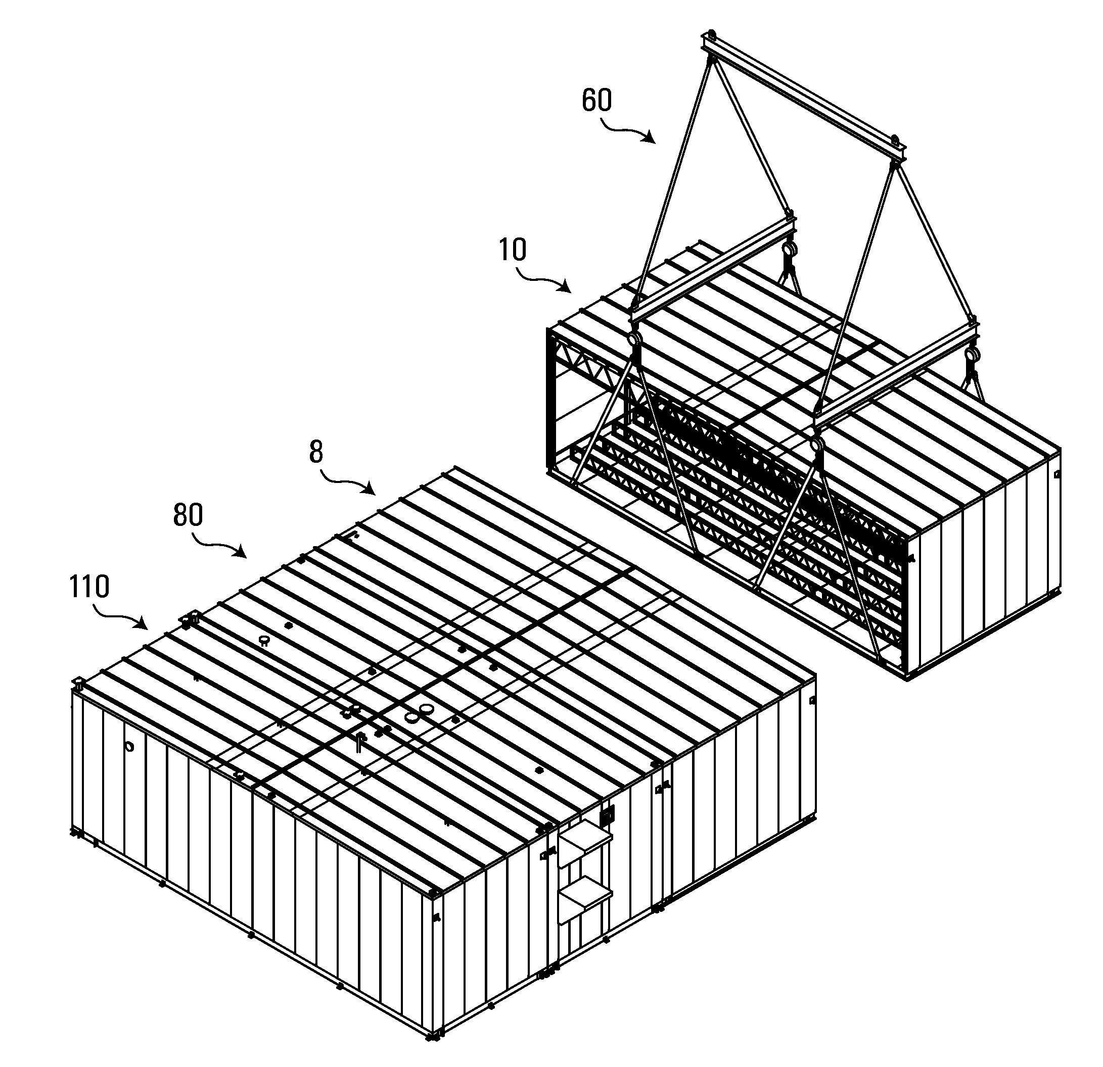
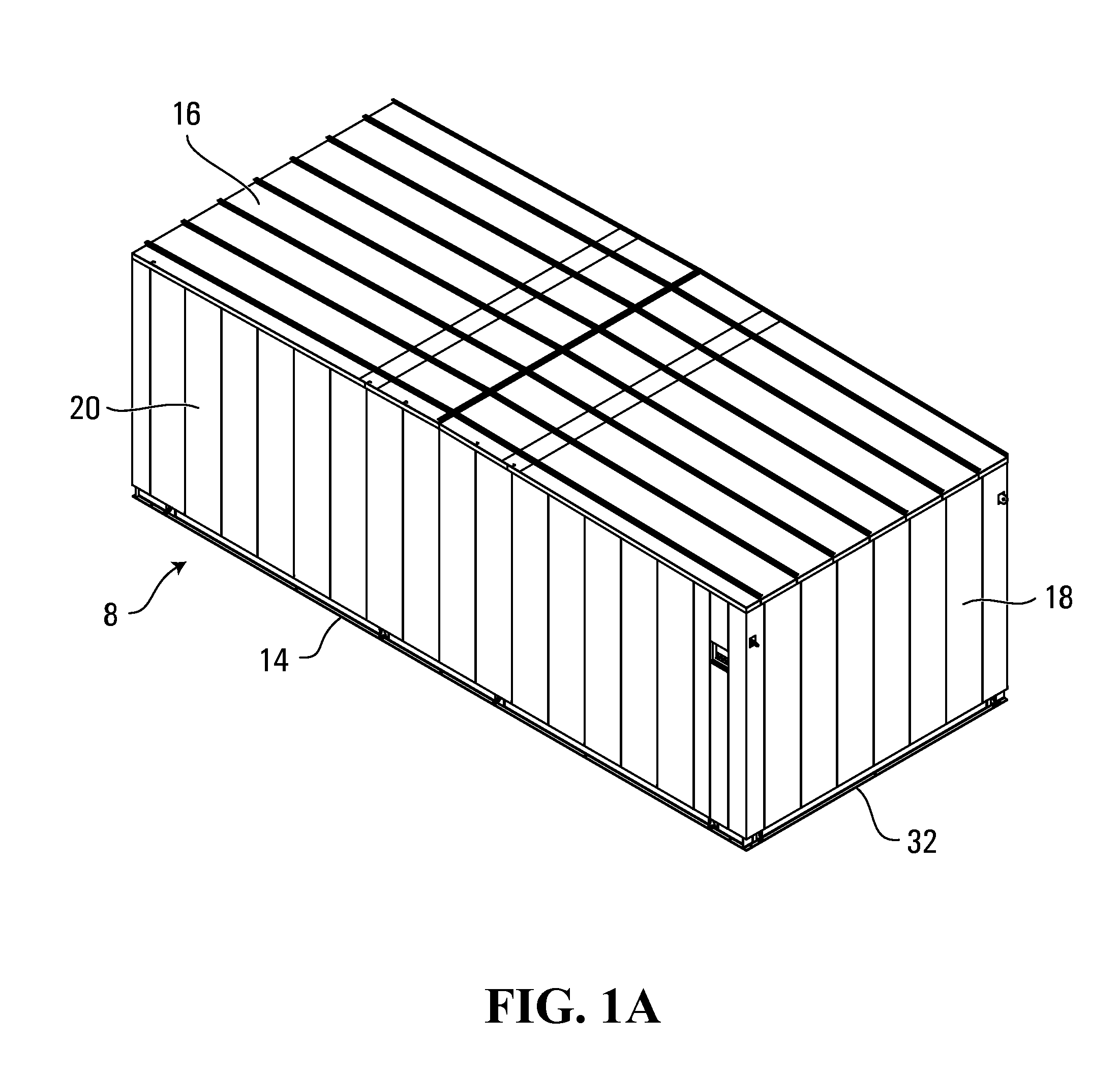
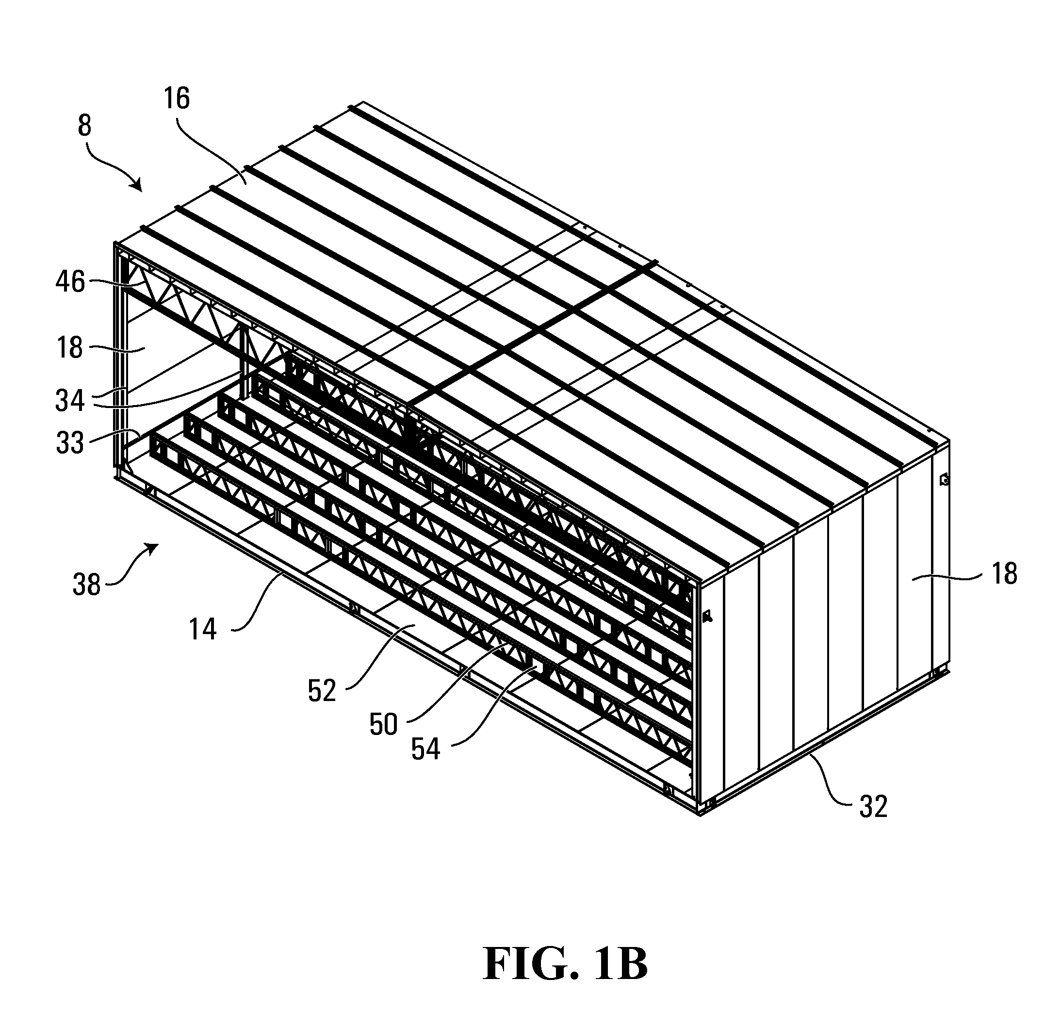
[0053]FIGS. 1A-1C, 2A-2B and 3A-3C show modular building units. FIGS. 1A-1C show a first side unit 8, FIGS. 2A-2C show an intermediate unit 10, and FIGS. 3A-3C show a second side unit 12. The units 8, 10 and 12 may be used, for example, for the construction of a modular computer room. In FIGS. 1A-1C, 2A-2B and 3A-3C, the same reference characters are used to identify the same features. The differences between the units 8, 10 and 12 will be identified.

[0054]The units 8, 10 and 12 have a base 14, a roof 16 and two opposed end walls 18. The first side unit 8 also has a first side wall 20. The second side unit 12 also has a second side wall 22. In FIGS. 1C, 2B and 3C, the units 8, 10 and 12 are shown without walls, roofs, floor plates and floor trusses for ease of viewing internal features.

[0055]As noted above, the units 8, 10 and 12 include a base 14. In the present embodiment, the base 14 is formed with a frame 24 (FIGS. 1C, 2B and 3C). The frame 24 defines a rectangular perimeter of ...


PUM


Abstract

A modular building unit for use in constructing a building comprises a top, a base, two opposed ends and at least one open side. The at least one open side extends between the two opposed ends and is free of upwardly extending structural supports. The modular building unit is configured to be interconnected to a second modular building unit along the at least one open side. The building unit is dimensioned to enable the building unit to be accommodated at or within a predetermined width limit for transportation before assembly and the building unit and the second modular building unit, when assembled, exceeding the predetermined width limit.

Description

FIELD[0001]The following relates to a modular building system and method. The system includes modular units that may be constructed at a manufacturing facility and then be transported to a construction site for assembly.BACKGROUND[0002]The power plants and computer rooms of buildings are often large and complex systems with a large amount of interconnected equipment. These systems can be incorporated into a main building. However, it may be advantageous to house such facilities in a separate building. This allows the main building to be reserved for other uses and allows easier access to the equipment in the separate building.[0003]The complexity of the systems also means that it may be advantageous to assemble, interconnect and test the equipment in a manufacturing facility and then ship the completed system to the construction site. One way this has been done is to use a shipping container as a building in which to assemble the equipment. The equipment is assembled and tested and ...

Claims


Application Information

Patent Timeline
IPC IPC(8): E04H1/00E04G21/14
CPCE04H5/02E04B1/3483E04H2005/005
Inventor WIEDERICK, CHRISGILLESPIE, DARRYLMCALLISTER, STEVEJOHNSTON, BRUCE
Owner EPSILON INT
Why Eureka
Try Eureka