Gas operating system for a firearm

a gas-operated, fully and semi-automatic technology, applied in the direction of weapons, weapon components, etc., can solve the problems of less precise firearms, inferior accuracy potential of systems relative to other systems, and complex barrel harmonics, so as to improve the appreciation of contributions to the art

Active Publication Date: 2012-11-08
MCMILLAN GROUP INT
View PDF13 Cites 6 Cited by
  • Summary
  • Abstract
  • Description
  • Claims
  • Application Information

AI Technical Summary

Problems solved by technology

However, when gas systems used for self-loading rifles are connected to barrels, the barrel harmonics are greatly complicated, and it is accepted that such systems have inferior accuracy potential relative to other systems, even when optimized.
In contrast, the gas tubes and cylinders of gas-operated firearms resist the whipping, flexing action of the barrel in unpredictable ways, making the firearm less precise.

Method used


Image

  • Gas operating system for a firearm
  • Gas operating system for a firearm
  • Gas operating system for a firearm

Examples


first embodiment

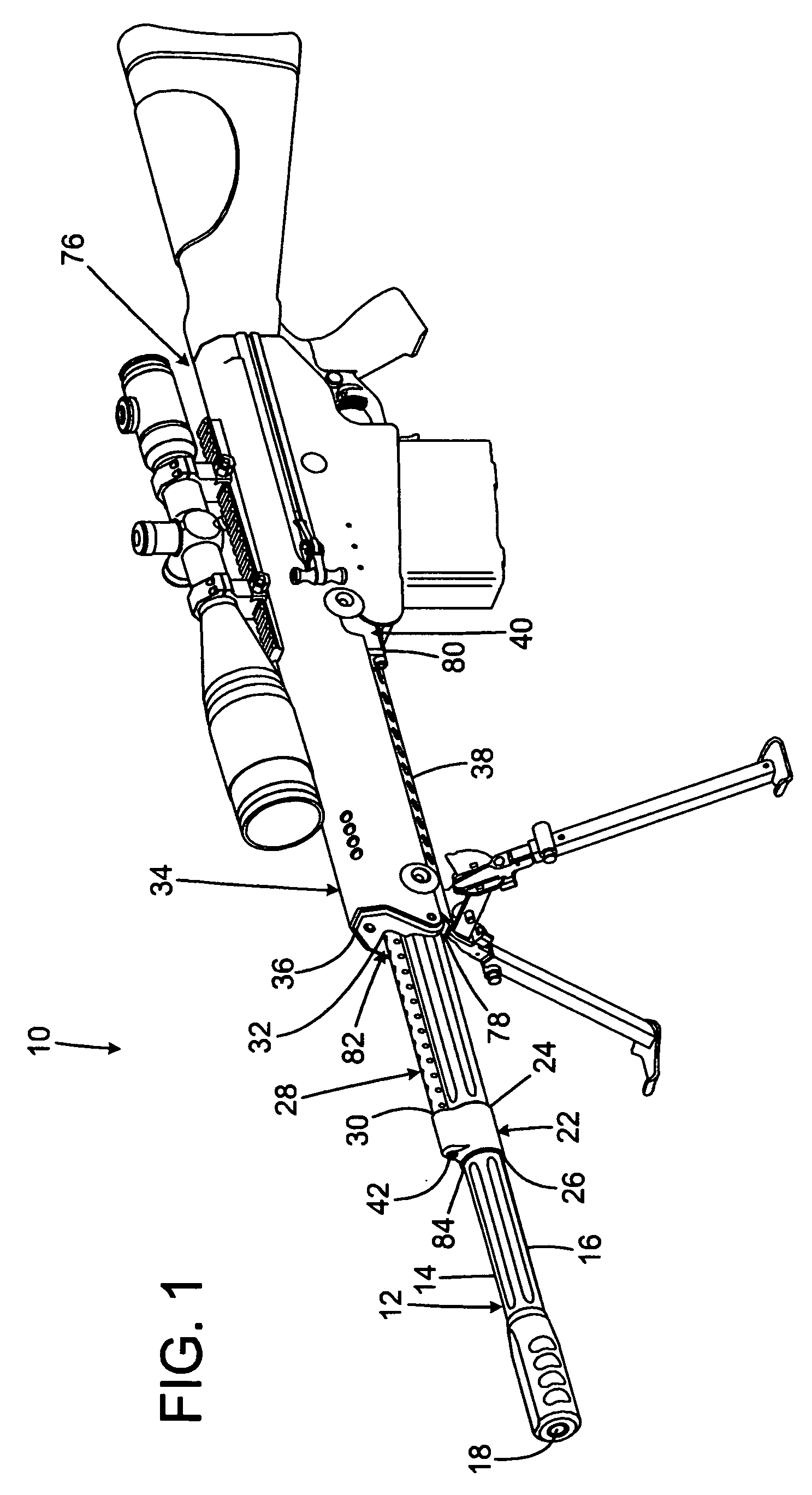
[0026]the gas operating system for a firearm of the present invention is shown and generally designated by the reference numeral 10.

[0027]FIG. 1 illustrates a rifle 76 including a gas operating system for a firearm 10 of the present invention. More particularly, the rifle 76 has a breech ring 40, stand-off assembly 38, receiver 34, and barrel 12. The muzzle 18 of the barrel protrudes forwardly from the front 36 of the receiver and the front 78 of the stand-off assembly. The breech ring extends rearwardly from the rear 80 of the stand-off assembly. A gas block 22 has a central bore 84 that slidably receives the barrel. A gas tube guard tube 28 surrounds a gas tube 50 (visible in FIGS. 2A and 2C).

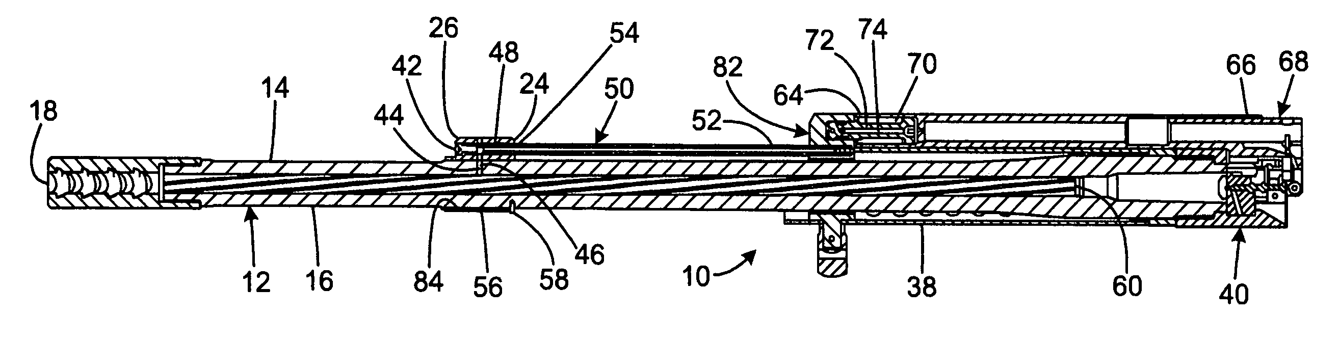
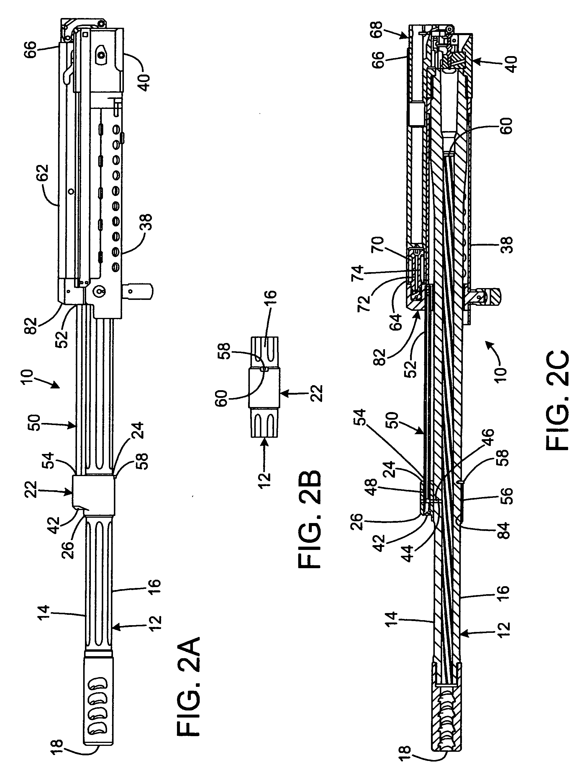
[0028]FIGS. 2A-2C illustrate the first embodiment of the gas operating system for a firearm 10 of the present invention. More particularly, a stop 82 is attached to, and extends forward from, the stand-off assembly. A stationary gas piston 72 is attached to the stop 82 for engagement with a c...

second embodiment

[0033]FIGS. 3A-3B illustrate the gas operating system for a firearm 100 of the present invention. More particularly, a stop 182 is attached to, and extends forward from, the stand-off assembly 138. A stationary gas piston 172 is attached to the stop for engagement with a cylindrical bore 170 in the front 164 of the breech block carrier 162. The gas piston seals the front opening of the cylindrical bore so the cylindrical bore acts as a moving gas cylinder. The rear end 152 of the gas tube 150 is rigidly attached to the stop 182 to communicate with the gas piston, while the front end 154 of the gas tube is received within a gas cylinder bore 148 extending through the gas block 122. The front end of the gas tube floats within the gas block cylinder in a slidable relationship. A small annular space 156 separates the gas block cylinder from the front end of the gas tube. This small annular space incorporates a labyrinth seal. The gas tube is plugged at its front end. The location of the...

third embodiment

[0036]FIGS. 4A-4B illustrate the gas operating system for a firearm 200 of the present invention. More particularly, a stop 282 is attached to, and extends forward from, the stand-off assembly 238. The rear end 252 of a gas cylinder 250 is rigidly attached to the stop while the front end 254 of the gas cylinder floats in a cylindrical bore 248 in the gas block 222. The front end of the gas cylinder is plugged. The gas block is rigidly clamped to the barrel 212. The location of the gas block coincides with a gas orifice 244 in the top 214 of the barrel. There is a small annular space 256 between the cylindrical bore in the gas block and the front end of the gas cylinder. This annular space incorporates a labyrinth seal. A gas piston 272 is located inside the gas cylinder.

[0037]When a cartridge is fired within the barrel, pressurized gas from the barrel enters the front end of the gas cylinder via the gas orifice in the barrel and a gas block passage 246 in the gas block. Gas flows re...


PUM


Abstract

A gas operating system for a firearm has an energy transmission facility and a gun barrel having a lateral aperture. The energy transmission facility and the lateral aperture have gas communication between them. The gun barrel and the energy transmission facility are mechanically decoupled such that the energy transmission facility does not impede flexing of the gun barrel. All forward forces generated by the energy transmission facility may be transferred from the energy transmission facility to a self-loading facility. The energy transmission facility may include a gas block having a sleeve that is slidably disposed on the gun barrel. The energy transmission facility may include a gas block and a tubular body extending from a receiver to the gas block, one end of the tubular body being slidably received in the gas block. The energy transmission facility may also include the tubular body receiving a gas piston.

Description

FIELD OF THE INVENTION[0001]The present invention relates to fully and semi-automatic, magazine fed, gas-operated firearms of the type where the operating gas is obtained from a hole drilled through one wall of the barrel, and more particularly to means for improving the accuracy of such systems.BACKGROUND OF THE INVENTION[0002]When a rifle is fired, the barrel is observed to “whip” or flex, and the point of impact of the projectile varies depending on the position of the muzzle when the projectile exits. Best precision is achieved when factors are controlled to permit the projectile to exit when the barrel is at a stationary maximum excursion, so that minute variances in projectile exit time have a minimal effect on the point of impact. Such barrel harmonics are relatively predicable in free-float barrels used for precision shooting, typically with bolt actions. However, when gas systems used for self-loading rifles are connected to barrels, the barrel harmonics are greatly complic...

Claims


Application Information

Patent Timeline
Patent Type & Authority Applications(United States)
IPC IPC(8): F41A5/18F41A5/26
CPCF41A5/26
Inventor DIECKMANN, RALF ECKEHART
Owner MCMILLAN GROUP INT
Why Eureka
Try Eureka