Barrel nut assembly and method to attach a barrel to a firearm using such assembly

Active Publication Date: 2014-02-06
LWRC INTERNATIONAL
View PDF5 Cites 81 Cited by
  • Summary
  • Abstract
  • Description
  • Claims
  • Application Information

AI Technical Summary

Benefits of technology

[0014](d) To provide a fixture which minimizes, or eliminates, the transfer of torque to the receiver of a firearm resulting from the use of a barrel nut, or barrel nut assembly, during the installation of a barrel.
[0015]In accordance with one embodiment of the present invention, a barrel nut assembly including a barrel nut and a locknut for coupling a barrel to the receiver of a firearm are provided. The barrel nut has internal threads and an external flange which is designed to be held in a fixture that is secured in a vice during barrel installation. The barrel nut body is designed to receive the threaded extension of the upper receiver in its back side and the chamber end of the barrel in its front side. An annular locknut, which has a central opening to receive the barrel, is used to secure the barrel to the host firearm's receiver. A preset torque value is applied to secure the locknut, and thereby the barrel, into place. While the locknut is being rotated, the barrel nut and upper receiver are held securely in a fixture which prevents the unintentional rotation and resulting misalignment of the barrel nut in relationship to the upper receiver. Further, the locknut places torque directly against a portion of the barrel, effectively compressing it against the front part of the upper receiver. The barrel nut assembly design and method of installation according to the present invention eliminate the problems inherent in the prior art as a result of applying an inappropriate torque value to a barrel nut in an effort to align the barrel nut with the gas tube of the firearm's operating system during barrel installation.
[0016]The body of the barrel nut also includes an integral bushing whi

Problems solved by technology

Both of these conditions present a variety of potential problems which include, but are not limited to, damage to the firearm, poor accuracy during normal operation or compromised operational reliability.
The vast majority of these new piston driven designs rely on the prior art barrel nut common to the M16 family of firearms and as such have inherited the flaws of this design.
In addition to the trouble which can result from improper torque being applied to the barrel nut, these piston designs depend on a moving piston, which is supported by the spokes of the barrel nut, to operate.
However, the spokes of the barrel nut were not designed for this purpose and, as a result, present a weak point in the operational reliability of these new piston driven designs.
Over time some systems which rely on the prior art barrel nut fail because the spokes which support the piston directly, or a removable bushing which houses the piston, start to bend or break, rendering the firearm inoperable.
Installation of the legacy AR15/M16 barrel nut, even when done properly, results in the transfer of torque from the barrel nut to the firearms receiver during installation of the barrel.
This can result in the warping

Method used


Image

  • Barrel nut assembly and method to attach a barrel to a firearm using such assembly
  • Barrel nut assembly and method to attach a barrel to a firearm using such assembly
  • Barrel nut assembly and method to attach a barrel to a firearm using such assembly

Examples


Embodiment Construction

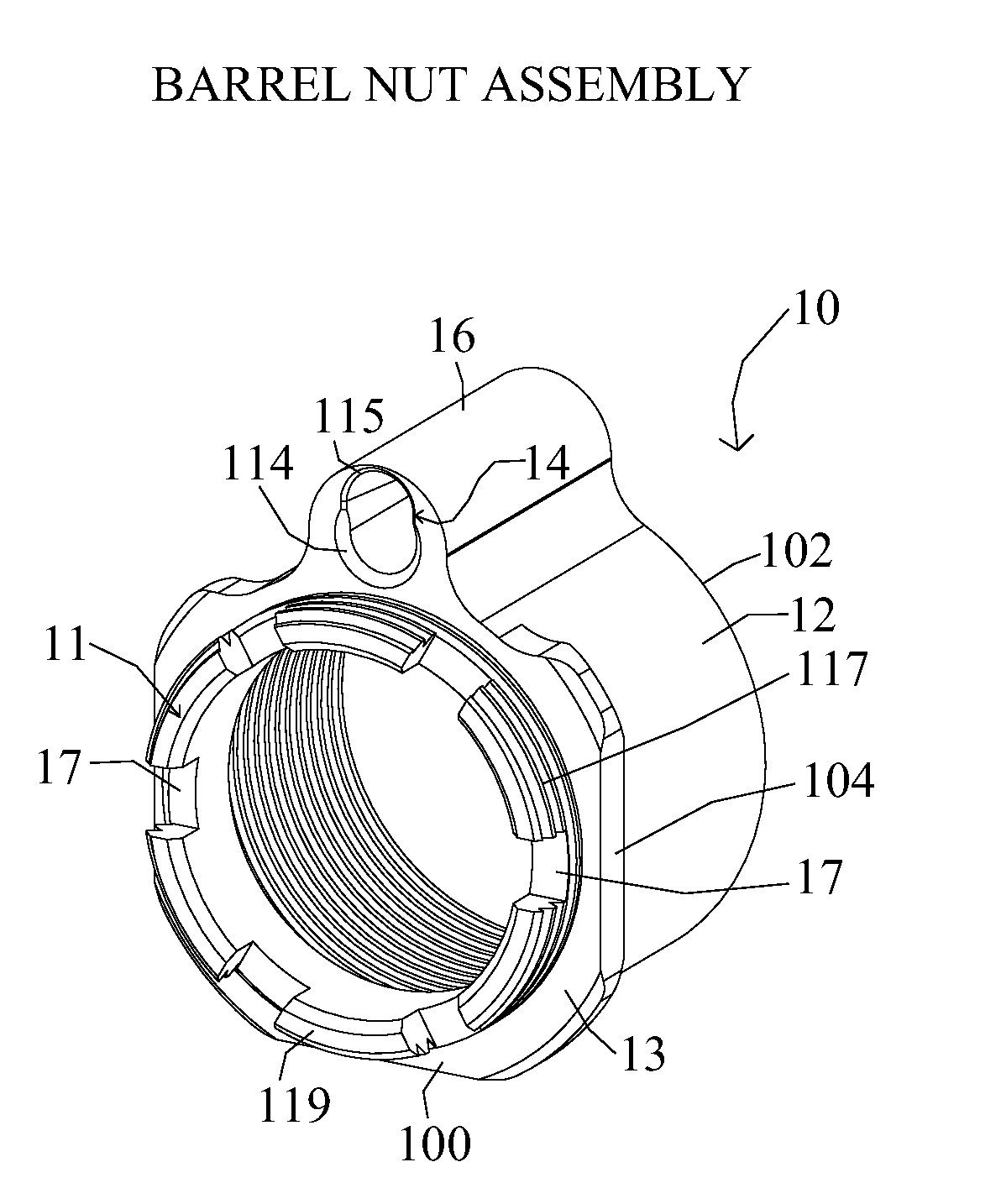
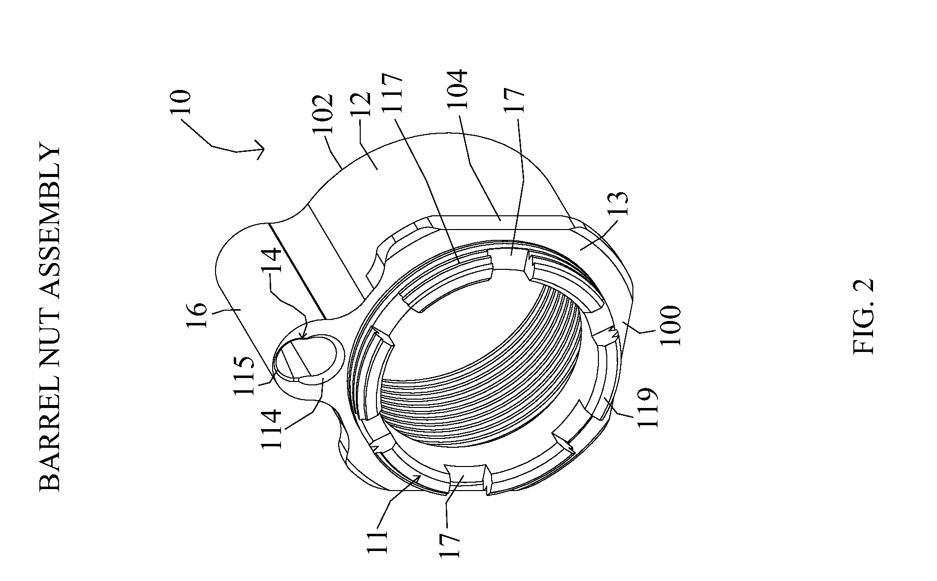
[0044]The present invention is directed to a barrel nut assembly for use with the AR-10, AR-15, SR25, M16 firearms and other derivatives to include those which use a gas piston in place of a conventional gas tube. Unless otherwise specified, the various components which make up the trigger mechanism, upper receiver assembly, lower receiver assembly, buttstock assembly, bolt assembly and barrel assembly are those found on the prior art M16 and M4 rifles and their various embodiments.

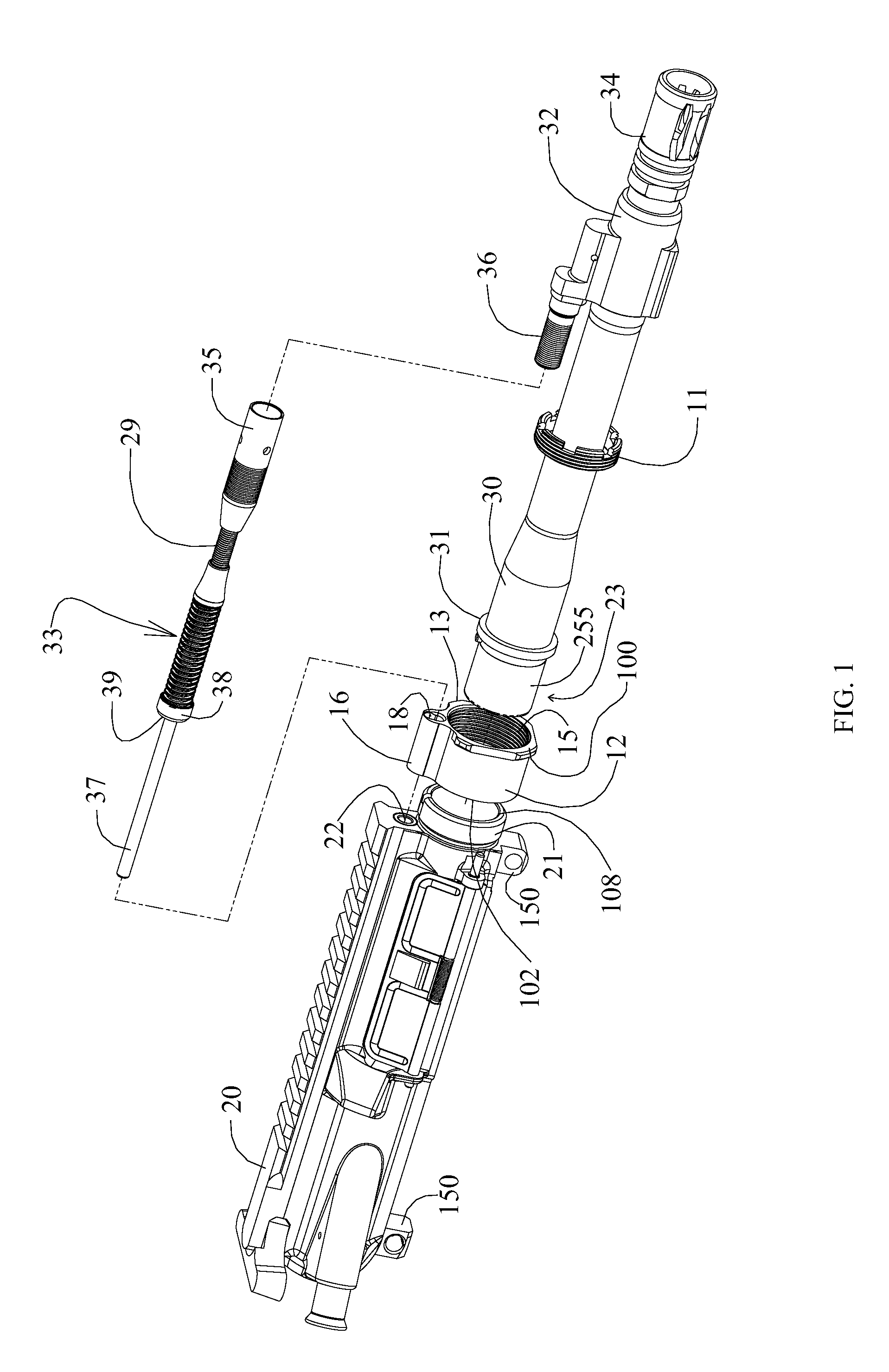
[0045]As used herein, the word “front” or “forward” corresponds to the end nearest the barrel (i.e., to the right as shown in FIG. 1); and “rear” or “rearward” or “back” corresponds to the direction opposite the end of the barrel, where the receiver is located (i.e., to the left as shown in FIG. 1).

[0046]The present invention is directed to a barrel nut assembly for securing a barrel to the front end of a receiver. In FIG. 1 there is illustrated an exploded perspective view of a firearm upper receiver gro...


PUM

PropertyMeasurementUnit
Lengthaaaaaaaaaa
Torqueaaaaaaaaaa

Abstract

A fixture for use with AR15/M16 type firearms is provided herein. The fixture is made up of several parts that when used in conjunction with one another mitigate the transfer of torque from the barrel nut to the firearms receiver during barrel installation. The fixture affords the user a method and apparatus that holds the barrel in alignment with the firearm receiver and secures the barrel against rotational movement during installation of a barrel nut or similar device. The fixture may be configured to work with the legacy AR15/M16 type barrel nut, as well as other designs as disclosed herein.

Description

[0001]This is a continuation-in-part application claiming benefit of U.S. application Ser. No. 13 / 562,651, filed Jul. 31, 2012, hereby incorporated by reference as if set forth herein in its entirety.BACKGROUND OF THE INVENTION[0002]1. Field of Invention[0003]The invention relates in general, to firearms, and more particularly to fixtures which mitigate the transfer of torque from the barrel nut to the firearms receiver during installation of the barrel.[0004]2. Description of the Related Art[0005]Firearms in the M16 family, which include but are not limited to, the AR10, SR25, AR15, and piston driven systems and other similar designs, have been in use with military, police, and civilian shooters for nearly 50 years. The M16 family of firearms includes a lower receiver having a stock coupled to the rear end which is connected to an upper receiver having a barrel coupled to the front end. The chamber end of the barrel is received by a portion of the upper receiver and threadedly secu...

Claims


Application Information

Patent Timeline
IPC IPC(8): F41A21/48
CPCF41A21/48Y10T29/49895F41A5/26
Inventor GOMEZ, JESUS S.
Owner LWRC INTERNATIONAL
Why Eureka
Try Eureka