Two-Fin Stackable Flechette Having Two-Piece Construction

a technology of two-piece construction and stackable flechettes, which is applied in the field of stackable flechettes or dartlike projectiles, can solve the problems of suboptimal flight characteristics of conventional flechettes, loss of significant portions of velocity and lethality, etc., and achieves optimal packing density, effective stacking, and maintain effective flight performance.

Inactive Publication Date: 2012-11-08
UNITED STATES OF AMERICA THE AS REPRESENTED BY THE SEC OF THE ARMY
View PDF19 Cites 5 Cited by
  • Summary
  • Abstract
  • Description
  • Claims
  • Application Information

AI Technical Summary

Benefits of technology

[0010]The flechette of the present invention has its concentration of mass centered in a forward section for stability with a center of pressure being located proximate to the root of the tail. In the tail section of the flechette, two tailfins are arranged in a flattened out “Z” or S-shaped formation when viewed from the aft end of the flechette. The flechette of the present invention is designed to allow for effective stacking while maintaining effective flight performance.
[0011]The flechette body is rectangular with an aspect ratio chosen so that the packing density is maximized, and the tailfins are rotated to an angle relative to the rectangular flechette body so that the tailfins of adjacent flechettes do not interfere with each other. Additionally, the tailfins of the flechette are angled to improve flight characteristics by inducing a spin to the flechette as it flies through the air. The wide separation between the center of gravity of the flechette and its center of pressure ensures that the flechette recovers quickly from any pitch or yaw angle (up to being completely reversed). Inducing a rolling moment to the flechette allows the perturbations caused by manufacturing imperfections to be integrated out of the flight path while the flechette is in flight.

Problems solved by technology

The first drawback is that their flight characteristics are suboptimal.
The elongated patterns indicate that conventional flechettes lose significant portions of their velocity and lethality attempting to recover a nose-first orientation after experiencing high transverse angular rate perturbations.

Method used


Image

  • Two-Fin Stackable Flechette Having Two-Piece Construction
  • Two-Fin Stackable Flechette Having Two-Piece Construction
  • Two-Fin Stackable Flechette Having Two-Piece Construction

Examples


Embodiment Construction

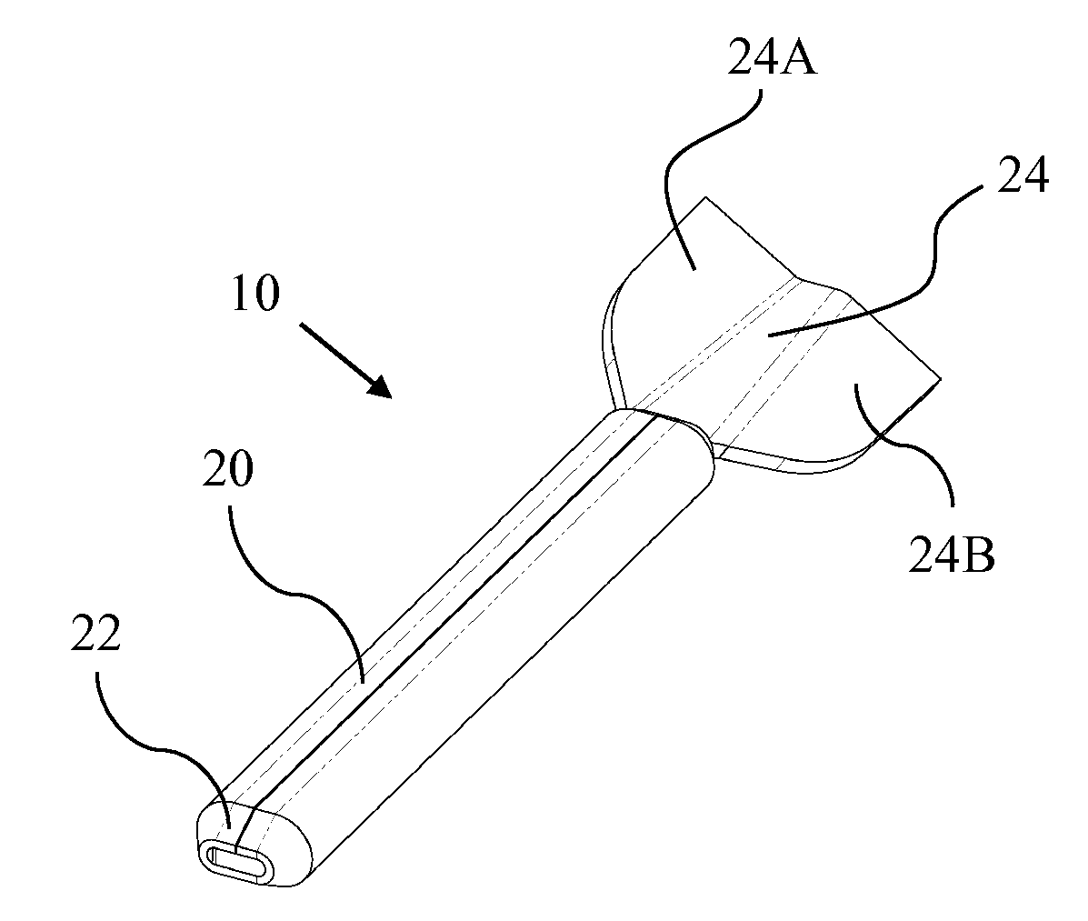
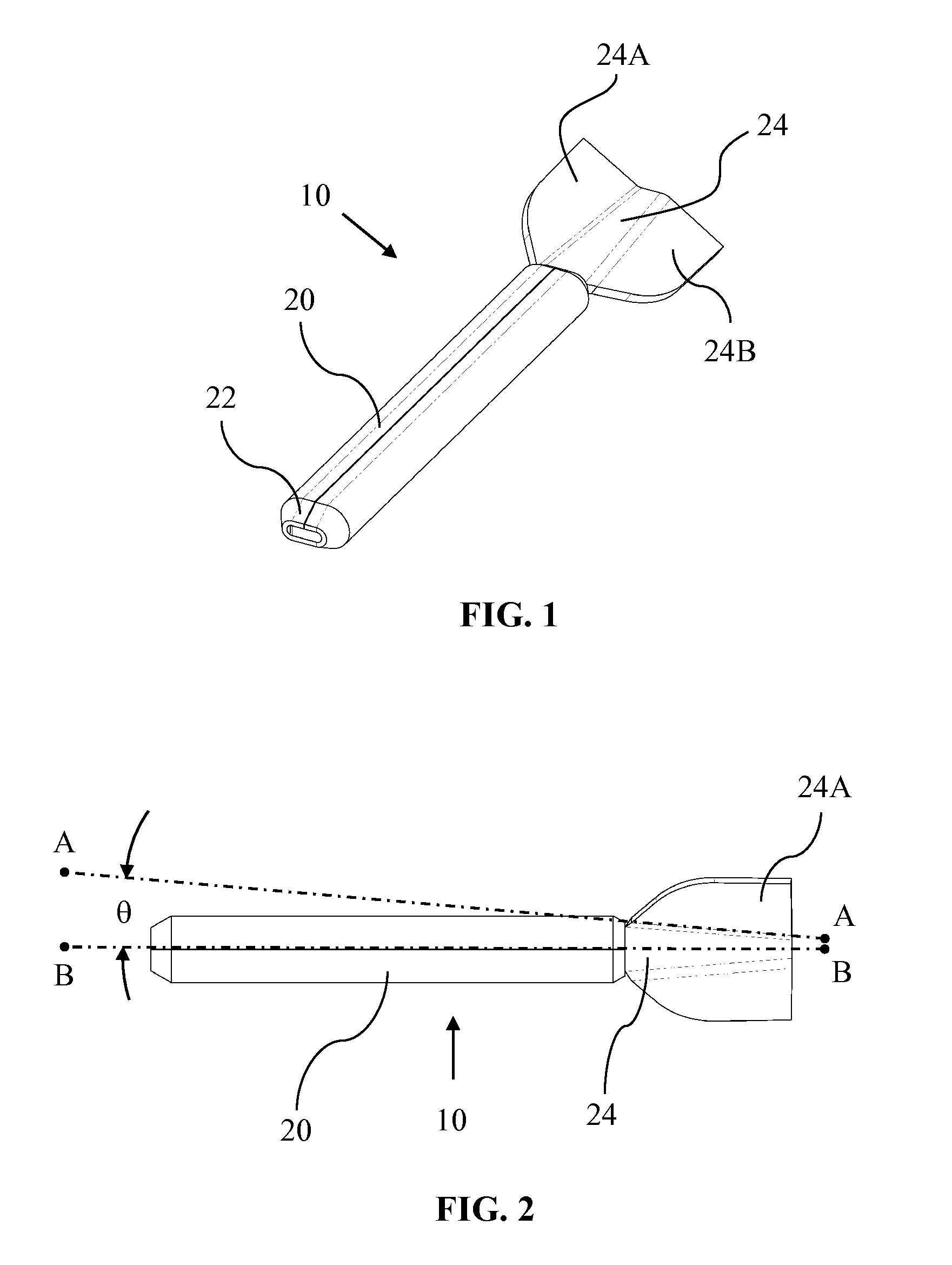
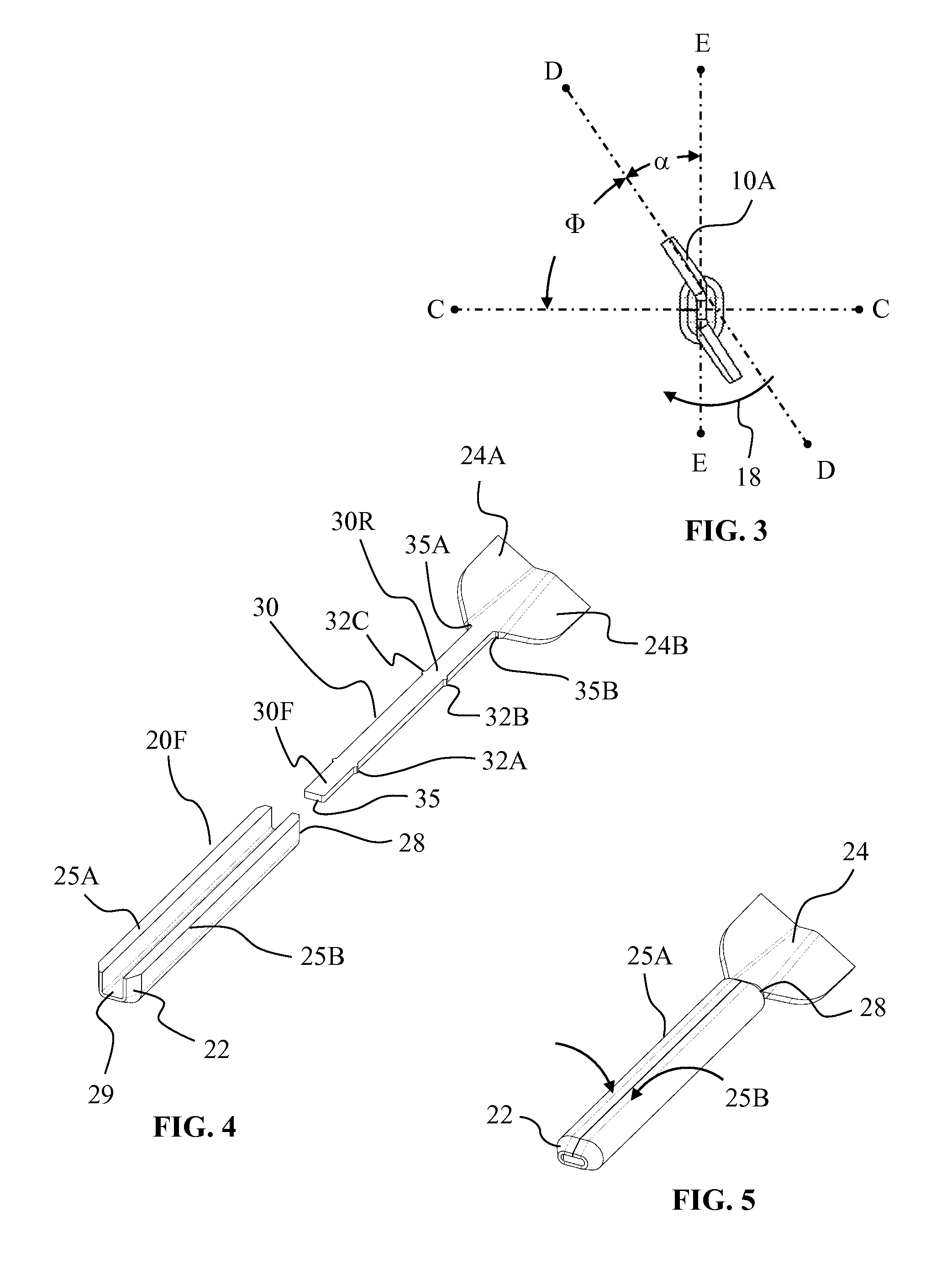
[0030]With reference to FIG. 1, the flechette 10 of the present invention has a forward body 20 which has a substantially rectangular box-like shape, with the forward body 20 having a front tip or nose 22. The forward body 20 is connected to a tail section 24 with the tail section 24 having two integrally connected tailfins or fins 24A, 24B located at the aft of the flechette 10. Both fins 24A, 24B are arranged so as to form a compound angularity which is represented by a longitudinal angle θ and a radial angle Φ (FIGS. 2 and 3).

[0031]In FIG. 2, angle θ is understood as being that angle formed by dotted lines AA and BB. Line AA represents the bend axis where the tailfin 24A adjoins the flat portion of the tail section 24 and line BB represents the longitudinal center line of the flechette 10. In a flight-tested prototype of the present invention, the angle θ measured 4.5 degrees.

[0032]With reference to FIG. 3, a radial angle Φ is formed by axis line CC and line DD. Line DD is coline...


PUM


Abstract

A flechette has a forward body (20) containing its center of gravity which is connected to a tail section (24). The tail section has a pair of fins (24A, 24B) each having a preselected longitudinal angle and radial angle. When the two fins are viewed from the aft of the flechette, the pair of fins demonstrate a S-shaped orientation. The size, shape and orientation of the pair of fins provide aerodynamic stability to the flechette while allowing the flechette to be stacked with like-shaped flechettes. The two-piece assembly of the flechette easily accommodates the use of different density materials for the respective pieces.

Description

[0001]This is a continuation-in-part of patent application Ser. No. 13 / 101,018 filed on May 4, 2011 and which is incorporated by reference herein.DEDICATORY CLAUSE[0002]The invention described herein may be manufactured, used and licensed by or for the U.S. Government for U.S. Government purposes without payment of any royalties thereon.BACKGROUND OF THE INVENTION[0003]1. Field of the Invention[0004]The present invention pertains to flechettes or dart-like projectiles.[0005]2. Discussion of the Background[0006]Conventional flechettes in the 60 grain to 150 grain weight class have been used successfully in weapons but suffer from two drawbacks. The first drawback is that their flight characteristics are suboptimal. High speed film of their flight shows that most of the flechettes dispensed from a warhead pitch and yaw significantly during their flight.[0007]It is understood that the pitch and yaw behavior, which slows the flechettes and reduces their lethality, is due to a combinatio...

Claims


Application Information

Patent Timeline
Patent Type & Authority Applications(United States)
IPC IPC(8): F42B10/08
CPCF42B6/003F42B39/007F42B12/362F42B10/08
Inventor BITTLE, DAVID A.WEBER, ROBERT V.
Owner UNITED STATES OF AMERICA THE AS REPRESENTED BY THE SEC OF THE ARMY
Why Eureka
Try Eureka