Valve device for fuel tank

a valve device and fuel tank technology, applied in the direction of functional valve types, liquid fuel feeders, machines/engines, etc., can solve the problems of excessive fuel supply, float valves are prone to sinking, etc., and achieve the effect of preventing an excessive fuel supply

Active Publication Date: 2012-11-08
NIFCO INC
View PDF5 Cites 3 Cited by
  • Summary
  • Abstract
  • Description
  • Claims
  • Application Information

AI Technical Summary

Benefits of technology

[0011]The present invention can provide the device that can establish ventilation between the inside and outside of the fuel tank, and that possesses the function of preventing an excessive fuel supply, without inviting complication in the structure while ensuring prevention of the excessive fuel supply.

Problems solved by technology

However, the device disclosed in Patent Document 1 is just simply provided with the through hole at the housing; therefore, the float valve is prone to lower immediately after it is detected that the fuel tank is filled up with the fuel.
When the fuel level inside the filler pipe lowers immediately after the fuel tank being filled up is detected, the automatic stop of the fuel supply gun is released, which enables immediate additional fuel supply, and invites excessive fuel supply.

Method used


Image

  • Valve device for fuel tank
  • Valve device for fuel tank
  • Valve device for fuel tank

Examples


Embodiment Construction

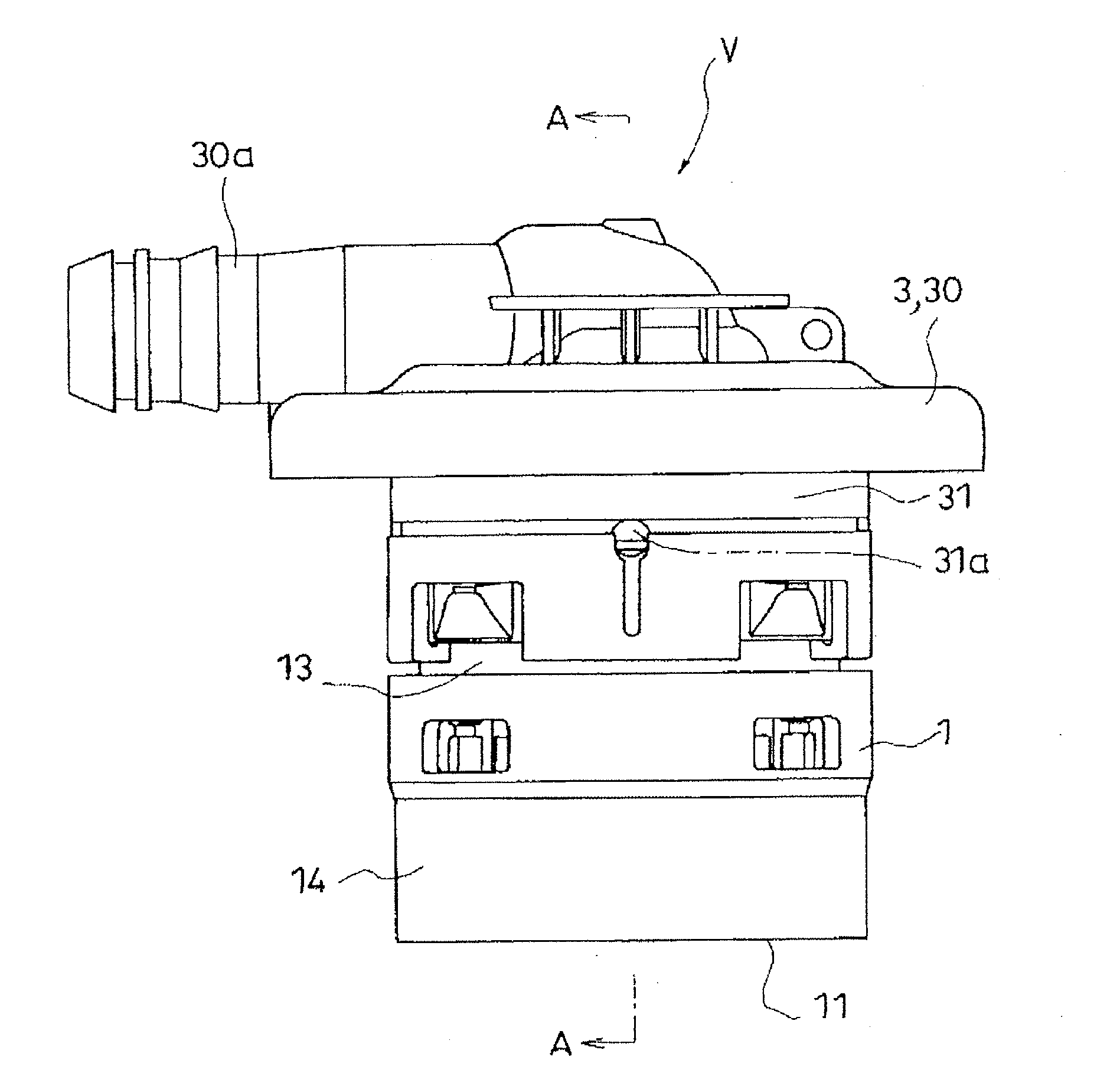
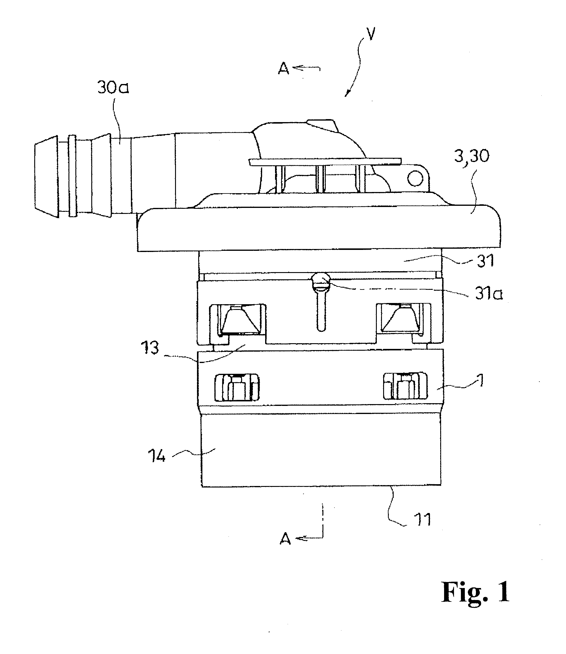
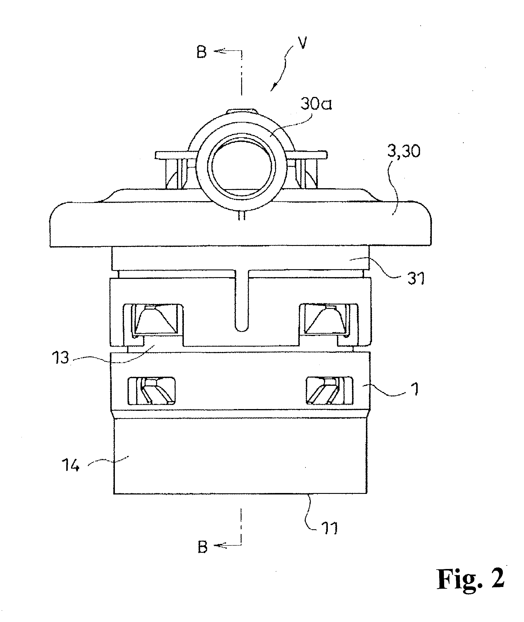
[0018]In the following, with reference to FIGS. 1 to 6, a description will be given of a representative embodiment of the present invention. A valve device V for a fuel tank according to the present embodiment is mounted on a fuel tank T of an automobile, a motorcycle or the like, to function to establish communication between an intra-tank Ta and an extra-tank Tb in the valve-opened state.

[0019]The valve device V includes a case 1 and a float element 2.

[0020]The case 1 is provided with, at its upper portion, a vent valve port 10 that communicates with the extra-tank Tb, and an inflow portion 11 for fuel is provided below the vent valve port 10. Further, at the upper face portion of the case 1, a ventilation portion 12 that establishes communication between the intra-tank Ta and the inside of the case 1 is formed above the waterline of the float element 2 when seated, which will be described later.

[0021]The case 1 is structured with an upper body 13 and a lower body 14. The upper bo...


PUM


Abstract

A valve device for a fuel tank includes a float element accommodated vertically movably in a case. The float element has a seal member at an upper portion thereof. The fuel flowing into the case through the inflow portion rises the float element to seat the seal member on the vent valve port. A ventilation portion connecting between inside of the tank and inside of the case is formed at an upper face portion of the case positioned above a waterline of the float element when seated. The upper face portion of the float element positioned in close proximity to the upper face portion reduces the amount of ventilation through the ventilation portion when seated. The valve device for a fuel tank further includes a regulation portion at the upper face portion of the case in which the interval is constant between the upper face portion of the case and the upper face portion of the float element when seated.

Description

TECHNICAL FIELD[0001]The present invention relates to an improvement in a valve device that is mounted to a fuel tank of an automobile, a motorcycle or the like, and that functions to allow communication between the inside and outside of the tank in the valve-opened state.TECHNICAL BACKGROUND[0002]Patent Document 1 discloses one of valve devices that have a fuel tank-use cutoff valve and means for detecting whether a fuel tank is filled up with fuel. The device includes an evaporator opening at the upper portion of a housing accommodating a float valve, and a fuel opening at the lowermost portion. When the fuel surface reaches the fuel opening by the fuel being supplied, the float valve rises and closes the evaporator opening. This allows the fuel level inside the filler pipe to rise, and the sensor of a fuel supply gun to detect that the fuel tank is filled up with the fuel, so as to stop the fuel supply. A through hole is provided at the upper portion of the housing of the device....

Claims


Application Information

Patent Timeline
Patent Type & Authority Applications(United States)
IPC IPC(8): F16K24/04
CPCB60K15/03519B60K2015/03576F02M37/0082F02M2025/0845B60K2015/03289B60K2015/0346F16K24/044Y10T137/3099B60K15/035B60K15/077F02M37/00
Inventor WADA, TOSHIO
Owner NIFCO INC
Why Eureka
Try Eureka