Unpowered apparatus for preventing backflow

a technology of unpowered apparatus and backflow, which is applied in the direction of valve actuation floats, functional valve types, valve operating means/releasing devices, etc., can solve the problems of sewage flowing back, flood damage, flooding of roads or water purification tanks and other facilities, etc., to enhance the performance of preventing backflow, prevent backflow, and facilitate drainag

Active Publication Date: 2012-11-08
KIM JONG SUN
View PDF3 Cites 9 Cited by
  • Summary
  • Abstract
  • Description
  • Claims
  • Application Information

AI Technical Summary

Benefits of technology

[0020]As described above, the unpowered apparatus for preventing backflow according to the present invention is characterized in that the installation of the apparatus is easy because it is installed at an end portion of a drain pipe, and a drainage can be quickly performed without any blockings even when a bulky and long impurity flows in along with sewage from a drain pipe, and a backflow phenomenon of sewage can be prevented in the present invention in such a way that an opening and closing door, which opens and closes a pipe passage in case of a backflow of sewage, quickly closes a pipe passage as it operates by mean of buoyancy.
[0021]In addition, the present invention helps enhance the performance of preventing backflow since an error operation does not occur in the opening and closing door in such a way that a gap formed between a pipe passage and an opening and closing door is blocked so that an impurity such as sand, debris, concomitant, etc. flowing in along with sewage from a drain pipe cannot interfere with the operation of the opening and closing door.

Problems solved by technology

So, the influent, which was not discharged through a corresponding drain pipe, overflows over a road or a ground surface, and at the same time, a discharge water pressure of a drain pipe passage rises and flows back toward a primary drain pipe where is lower than other areas, thus consequently flowing back to a drainage part and a water collection tank of a house or a public facility and an industrial facility which are sewage discharge places, thus causing a flooding damage and flooding a road or a water purification tank and other facilities.
In addition, in case that a branch drain pipe becomes a pipe water passage due to heavy fall or concentrated heavy rain in a certain area or the water level of a river sharply rises for a short time, and in case that the water level of a river rises for a long time due to seasonal rain, or in case that the water level of sea rises, the sewage and river water or sea water flow back toward the sewer pipes of a lower area or a branch drain pipe or toward an agricultural passage of a water canal, thus causing a flooding damage.
Since the prior art is however characterized in that the opening and closing part is opened only by means of the water pressure of the sewage, when the amount of sewage discharged via the drain pipe is small, the opening and closing part might not be open, which leads to a problem that sewage flows back by means of the opening and closing part which was closed due to the above-mentioned problem.
As the opening and closing part interferes with the flow of sewage, a smooth discharge of sewage is hard, and since the pipe passage of the connection pipe is hard to be formed in a full open type it is almost impossible to discharge a certain object which is bulky and long.

Method used


Image

  • Unpowered apparatus for preventing backflow
  • Unpowered apparatus for preventing backflow
  • Unpowered apparatus for preventing backflow

Examples


Embodiment Construction

[0027]The embodiments of the present invention will be described in details; however the disclosed embodiments are not limited thereto unless they escape from the gist.

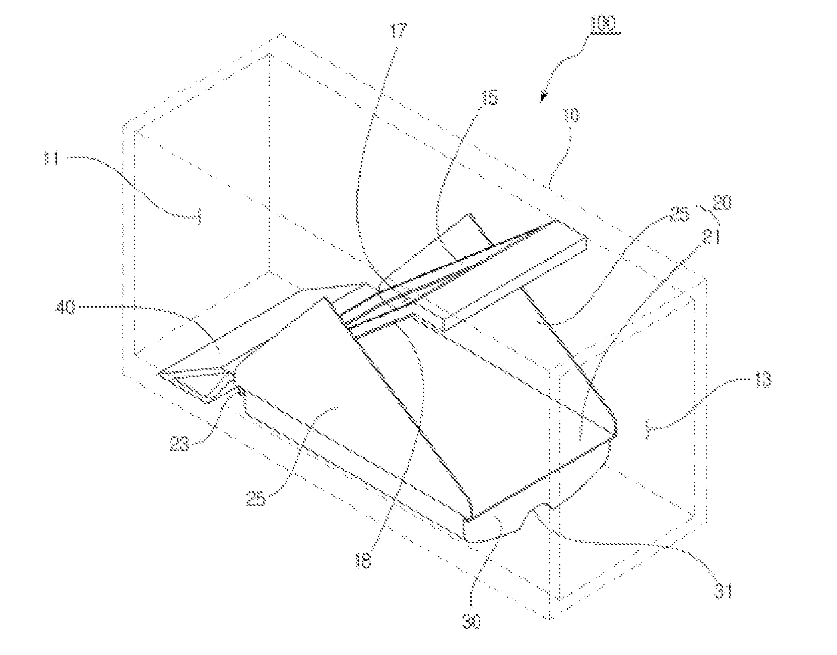
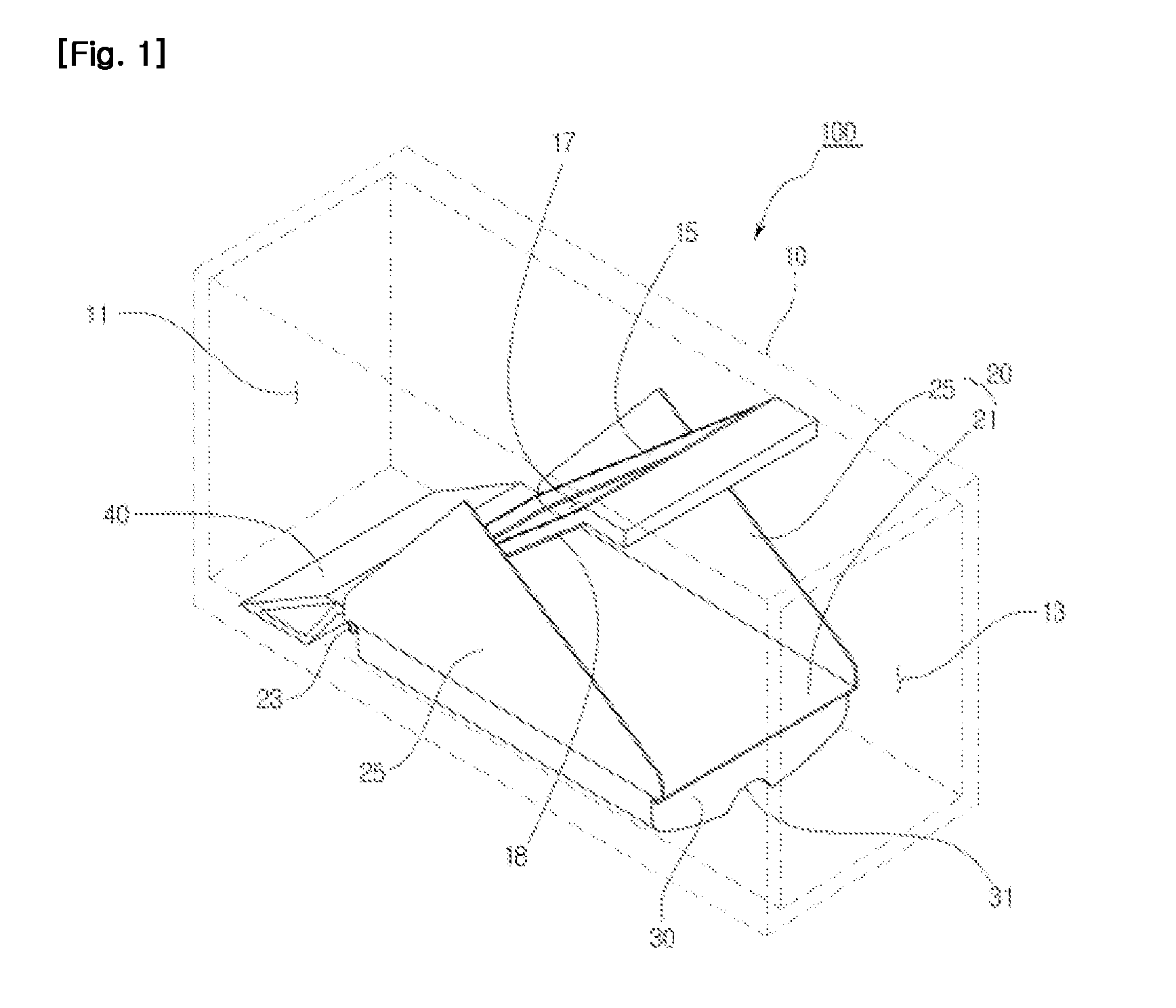
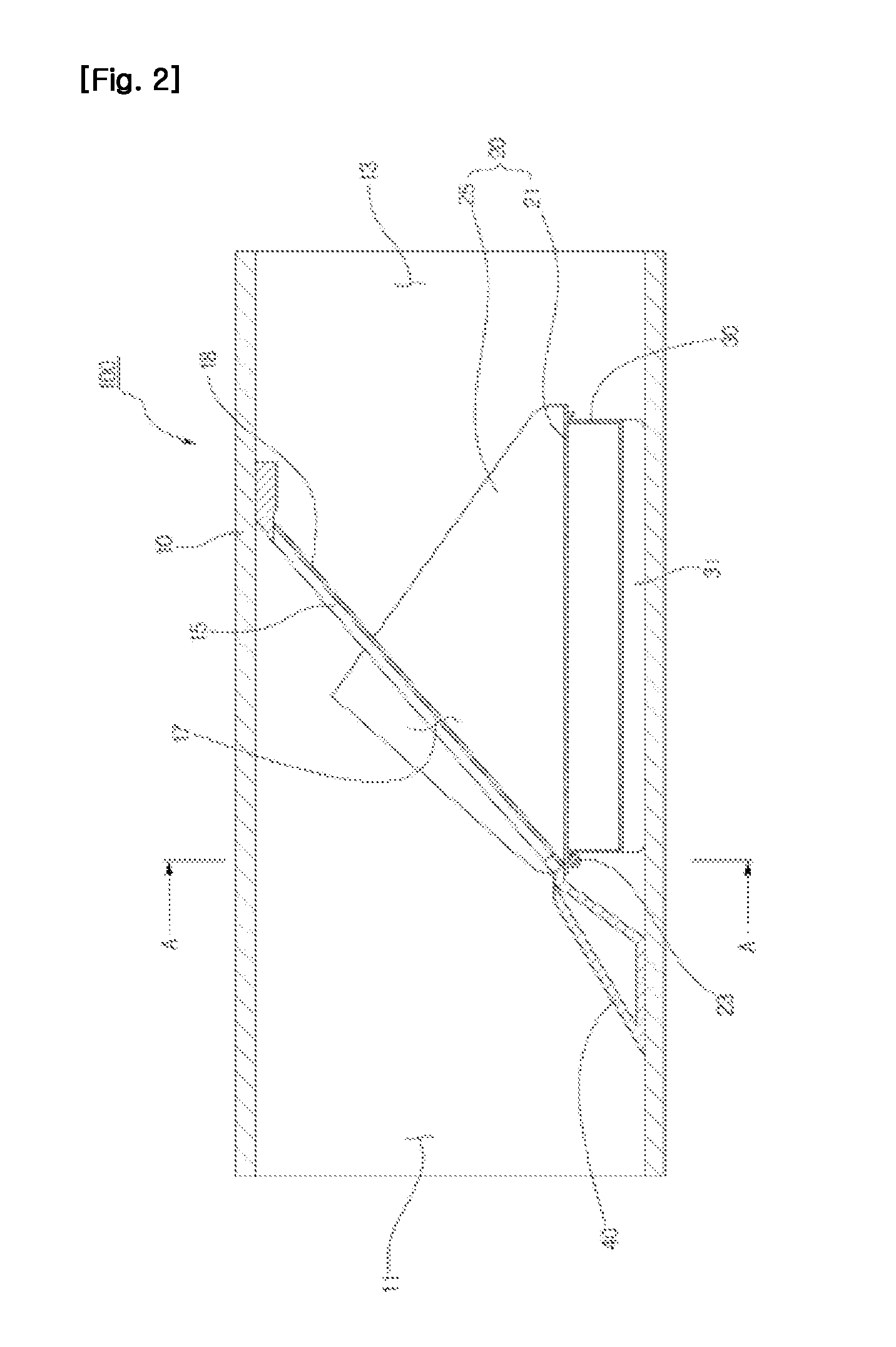
[0028]FIG. 1 is a perspective view illustrating a construction of an unpowered apparatus for preventing backflow according to the present invention. FIG. 2 is a side cross sectional view illustrating construction of an unpowered apparatus for preventing backflow according to the present invention. FIG. 3 is a cross sectional view taken along line A-A of FIG. 2 according to the present invention.

[0029]As shown in FIGS. 1 to 3, the unpowered backflow prevention apparatus 100 according to the present invention comprises a tubular body part 10 through which sewage comes in and goes out, an opening and closing part 20 opening and closing the inner side of the body part 10, a floating part 30 provided at the opening and closing door 20, and a guide 40 guiding the flow of sewage into the body part 10.

[0030]The body part 10 i...


PUM


Abstract

The present invention relates to an unpowered apparatus for preventing backflow, comprising: a tubular main body having a stepped portion, wherein the main body has an inlet port for the inflow of sewage, an outlet port for discharging the sewage, and a communication port which is inclined toward the outlet port and which puts the inlet port and the outlet port in communication; an opening/shutting door having a door body rotatably hinged to the inside of the main body so as to open/shut the communication port, and a pair of blocking plates extending from either side of the door body so as to block the space between the stepped portion and an inner wall of the main body; a floating part which is arranged in the opening/shutting door, the interior of which is empty such that the floating part can float on a water surface, and which provides the opening/shutting door with buoyancy and operates the opening/shutting door so as to close the communication port when the sewage flows back toward the outlet port; and a guide interposed between the stepped portion and a bottom surface of the main body so as to guide the sewage introduced from the inlet port such that the sewage flows toward the outlet port via the communication port.

Description

TECHNICAL FIELD[0001]The present invention relates to an unpowered apparatus for preventing a backflow, and in particular to an unpowered apparatus for preventing a backflow which is typically installed at an end portion of a drain pipe connected from a drainage well to a sewer pipe or installed at a water gate of an agricultural drainage canal for the purpose of preventing a backflow of sewage.BACKGROUND ART[0002]Sewage discharged from various drain pipes such as a residential facility, an agricultural facility, a public facility and an industrial facility is collected from a primary drain pipe to a drainage well, a sewer pipe or a sewage main pipe and a branch drain pipe and is directly discharged to a river or sea or sewage is collected in a sewage treatment facility such as a sewage end treatment plant or a sewage disposal plant and is discharged to a river or a public water surface such as sea.[0003]A primary drain pipe or a sewage main pipe and a branch drain pipe generally in...

Claims


Application Information

Patent Timeline
Patent Type & Authority Applications(United States)
IPC IPC(8): F16K15/00
CPCE03F7/04F16K31/22F16K15/03Y10T137/7358Y10T137/7898E03F5/042F16K31/18F16K33/00
Inventor KIM, JONG SUN
Owner KIM JONG SUN
Why Eureka
Try Eureka