Soil plug processing mechanism

a processing mechanism and plug technology, applied in the field of soil plug processing mechanism, can solve the problems of unfavorable use, high vibration, unfavorable use, etc., and achieve the effects of reducing vibration, simple removal, and smooth running

Active Publication Date: 2012-11-08
WIEDENMANN GMBH
View PDF11 Cites 3 Cited by
  • Summary
  • Abstract
  • Description
  • Claims
  • Application Information

AI Technical Summary

Benefits of technology

[0022]An advantage of a rotary sieve as compared to known separating devices is, in particular, the particularly smooth running as fewer vibrations than in the case of vibratory sieves or the like can occur through the rotational movement. Rotary sieves are preferably able to be removed, replaced and cleaned in an easy manner. For example, it is possible to provide several sets of rotary sieves with various grating arrangements, various grating mesh diameters, various shapes etc. In conjunction with a rotary sieve, it is also possible to provide active and passive processing elements, such as scrapers, blade elements arranged in the interior of the rotary sieves or other manipulating elements, such as brushes, impact elements or the like.
[0023]In addition, a bearing region, by way of which the rotary sieve is movably mounted on roller elements, has an out-of-round shape. The rotary sieve is mounted, for example, by way of its sieve outside surface on rollers such that the corresponding circumferential region of the sieve outside surface acts as a bearing region. If the sieve outside surface with the sieve area is then developed so as to be out-of-round, on the one hand this has considerable advantages for the production, as production of a circumferential sieve drum is achievable by individual bends of a flat sieve grating, on the other hand moving the out-of-round sieve drum outside surface over roller elements, acts like a striking mechanism to set the rotary sieve itself into shaking movements. When rotating over the out-of-round shape there is then additionally a vibratory movement which supports the separating procedure. For example, the outside surface of the sieve drum is realized as a prism which has several flat surfaces on its circumferential region. Each time a rotary sieve moves over the supporting rollers by way of an edge between said surfaces, there is a small impact onto the rotary sieve, which supports the separating procedure.
[0024]In addition to a bearing region, in an advantageous manner the rotary sieve also has a round drive region, by which the rotary sieve is rotatingly driveable. The round drive region can include, for example, a row of teeth running all the way around or a gear ring. Through engagement of a gear wheel as drive member, the rotary sieve can be set to rotate. The rotary sieve drive device can have an actively driven driving rotary member, such as, for example, a driving toothed wheel, which is connected or connectable, e.g. couplable to an engine or the like (e.g. power take-off shaft), and at least one intermediate rotary member, such as, for example, a toothed wheel which is mounted so as to rotate freely. In such a manner, a whole row of rotary sieves arranged in parallel can be driven in a simple manner by placing an intermediate toothed wheel, which is driven by the respectively driven rotary sieve and also drives the adjacent rotary sieve, between each adjacent rotary sieve.
[0025]The at least one rotary sieve or the majority of rotary sieves are preferably rotatably mounted in a rotary sieve bearing device in such a manner that the rotary sieves are movable in relation to a chassis of the soil plug processing mechanism. For example, there is provided a rotary sieve frame on which the rotary sieves are rotatably mounted. The rotary sieve frame is preferably mounted on the chassis so as to be pivotable and / or displaceable. By displacement, the rotary sieve can be moved, for example, out of an operating position in the machine into a handling position, where the rotary sieve is easily accessible, for example in order to exchange and / or clean the rotary sieve. An inclination of the axes of rotation is preferably able to be adjusted by pivoting the rotary sieve frame.
[0026]The rotary sieves are preferably developed in such a manner that they have an opening at both axial ends. The soil plugs can be introduced through a first opening and the coarse particles can be discharged through a second opening. The type of output and the conveying of the coarse particles and also the separation can be influenced by adjusting the axis of rotation. The inclination of the axes of rotation is preferably automatically adapted to a position of the chassis. For example, a rotary sieve bearing frame is attached in a floating manner such that when there is a change in the inclination of the chassis on account of travelling over inclined ground, the displacement of weight leads to the inclination of the axes of rotation being adapted. It is particularly preferred for the at least one rotary sieve to be removable and / or exchangeable without the use of tools. This can be achieved, for example, by the rotary sieve resting on bearing elements, such as supporting rollers and rotary members, and being simple to remove by lifting, in particular, in the handling position.
[0027]Preferably, an axial guiding device is provided which limits or avoids an axial movement of the at least one rotary sieve. The axial guiding device is preferably associated with the drive region and / or the bearing region. For example, a spigot and socket engagement extending in the circumferential direction can be provided. In a practical development, at least one of the rotary members has a projecting disc region for this which engages in a groove on the drive region. A drawer runner is provided, for example, as a displacement device for easy removal of the rotary sieves. Thus, for example, an entire unit of rotary sieves can be movably mounted on a drawer runner or another such displacement unit in order to achieve ease of removal and ease of manipulation.

Problems solved by technology

A disadvantage of the known machines is that the design of the machines is unwieldy and they are not comfortable to operate.
The known separating devices result in high levels of vibration and in signs of a great deal of wear and tear on sieves and moving parts.
The separating devices quickly become contaminated and have to be cleaned in an arduous manner.
As the drive device is movably mounted in order to enable contact with or disconnection of the picking up movement, such a belt and chain drive can be troublesome.

Method used


Image

  • Soil plug processing mechanism
  • Soil plug processing mechanism
  • Soil plug processing mechanism

Examples


Embodiment Construction

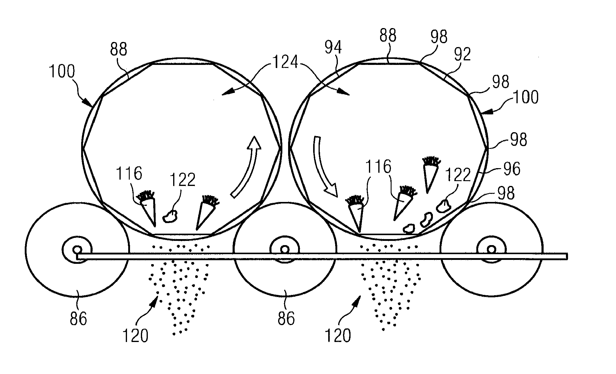
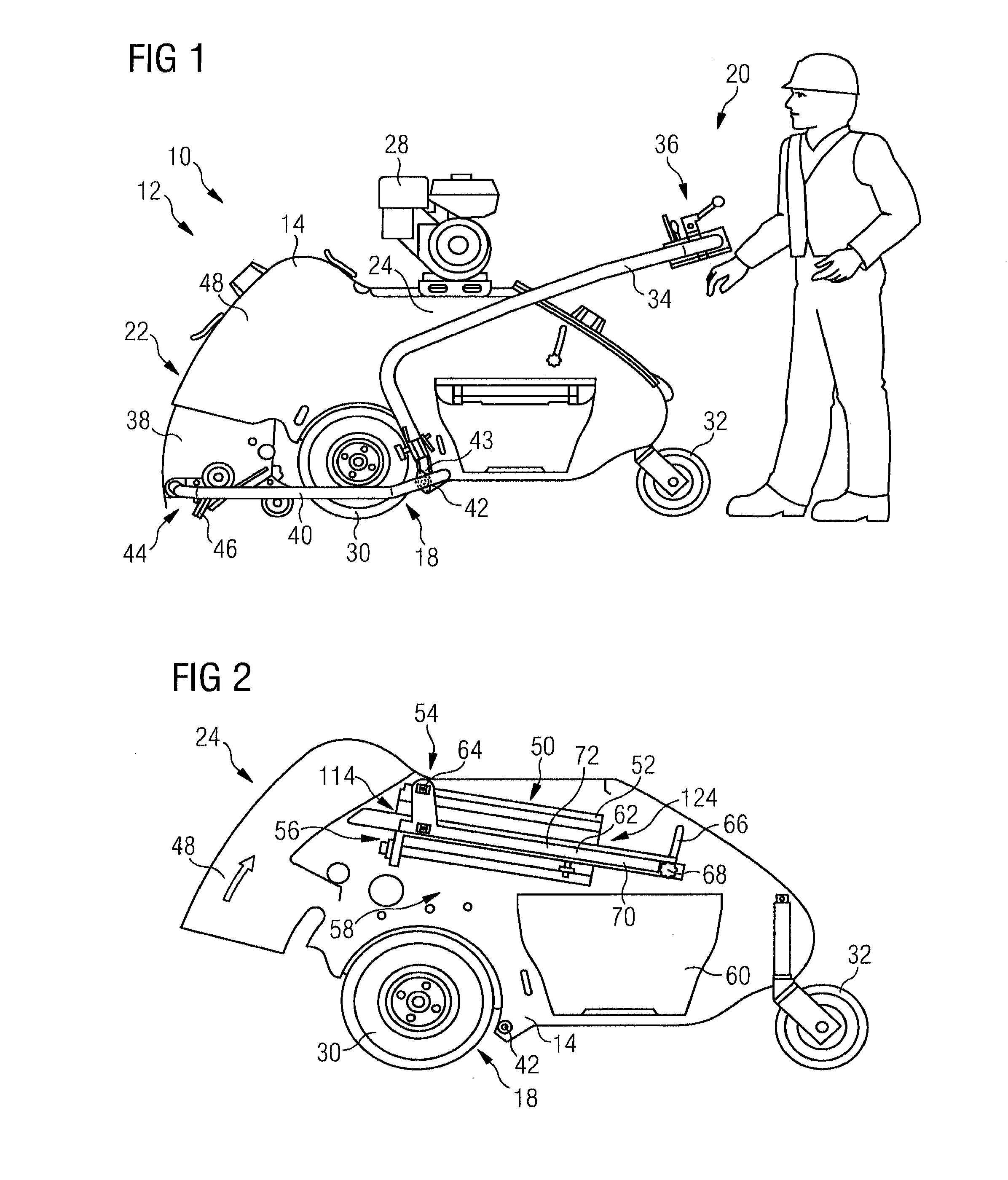
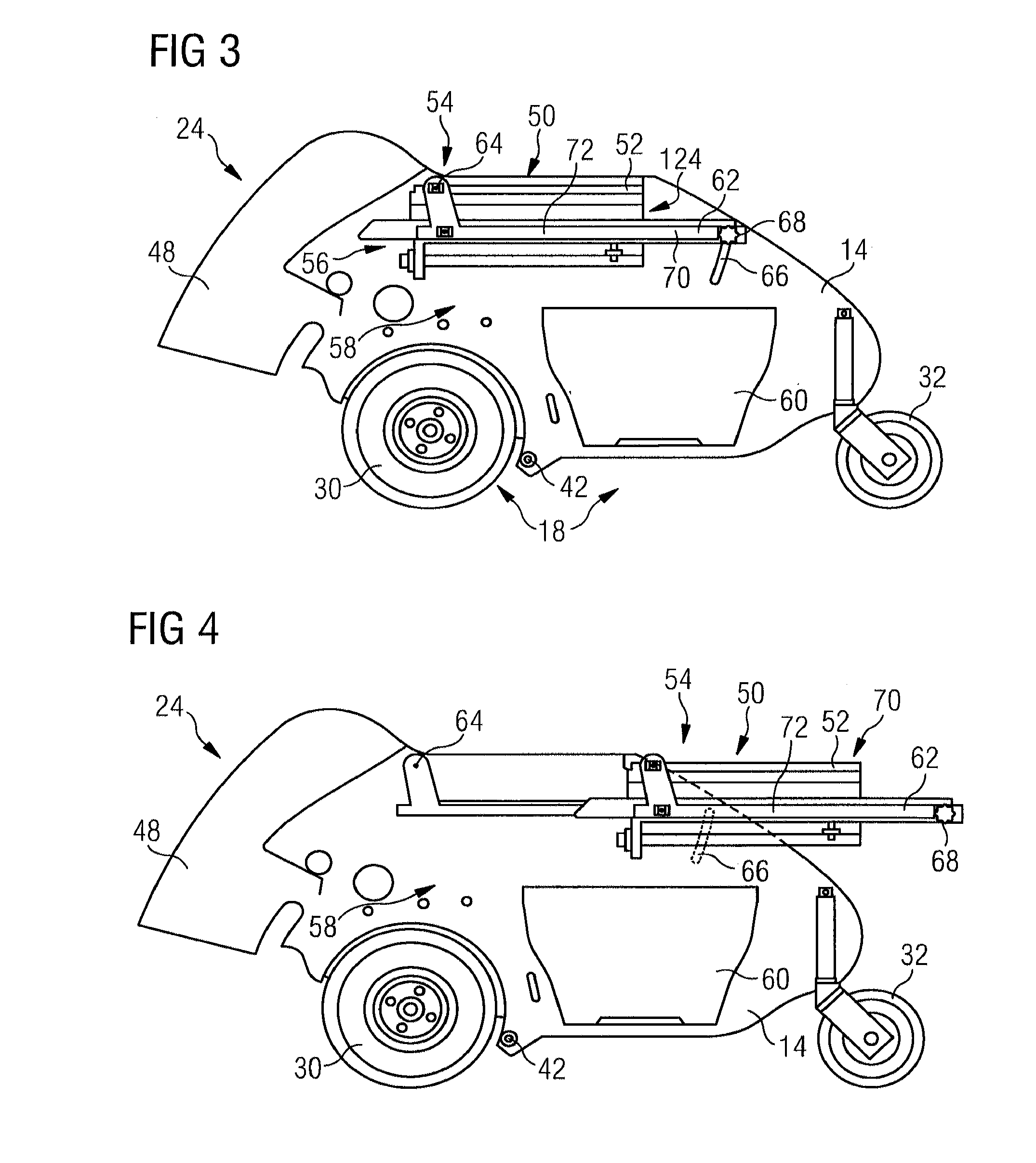
[0060]The ground maintenance machine 10 shown in more detail in FIG. 1 is realized as a cleaning machine 12 (in particular, e.g. a sweeping machine) for cleaning (e.g. by sweeping) areas of ground of pieces of soil or soil cores, referred to below as soil plugs, that occur during ground maintenance. The cleaning machine 12 has a chassis 14 (basic design or machine frame) with a framework 18 and a manual guiding device 20 in order to move the cleaning machine 12 over the ground. In addition, the cleaning machine 12 has a plug picking up device 22 for picking up soil plugs and a soil plug processing mechanism 24 for processing the soil plugs picked up. In the embodiment represented, the cleaning machine 12 is realized as a self-propelling machine which has an engine 28, in particular an internal combustion engine.

[0061]The framework 18 has drive wheels 30 and guide rollers 32. The drive wheels 30 are connectable to the engine 28 in a usual manner (not shown in any more detail) to driv...


PUM


Abstract

A soil plug processing mechanism for processing soil plugs which occur during ground maintenance. The soil plug processing mechanism having a separating device for picking up and processing the soil plugs by separating the soil plug material into fine particles and coarse particles. The separating device has at least one rotatable rotary sieve which has a rotatably driveable sieve drum with an outside surface which is configured at least partially as a sieve area.

Description

CROSS-REFERENCE TO RELATED APPLICATIONS[0001]This application claims priority under 35 U.S.C. §119(a) to German Patent Application No. 10 2011 075 472.5, filed in Germany on May 6, 2011, the entire contents of German Patent Application No. 10 2011 075 472.5 are hereby incorporated herein by reference.BACKGROUND[0002]1. Field of the Invention[0003]The present invention relates to a soil plug processing mechanism and to a ground maintenance machine and / or cleaning machine having such a soil plug processing mechanism. In addition, the present invention relates to particular parts for such a soil plug processing mechanism or such a machine.[0004]2. Background Information[0005]Soil plugs are created within the framework of ground maintenance, for example when the ground is being maintained using hollow spiking tools such as hollow spoons during deep loosening. In the case of a ground maintenance machine for the deep loosening of soils, such as is described, for example, in DE 10 2008 017...

Claims


Application Information

Patent Timeline
Patent Type & Authority Applications(United States)
IPC IPC(8): B07B1/22F16H7/12
CPCA01B45/023A01B45/04A01G20/12B07B1/22
Inventor PFISTERER, THOMAS
Owner WIEDENMANN GMBH
Why Eureka
Try Eureka