
Touch Panel

a technology of touch panel and display pattern, which is applied in the field of touch panel, can solve the problems of increasing power consumption, harmful to energy saving and environmental protection, and achieve the effect of improving the brightness of the display pattern without increasing the power consumption of the light-emitting devi

Active Publication Date: 2012-11-08
MOLEX INC
View PDF9 Cites 8 Cited by
  • Summary
  • Abstract
  • Description
  • Claims
  • Application Information

AI Technical Summary

Benefits of technology

[0006]The technical problem that the Present Disclosure intends to solve is to overcome the aforementioned drawbacks by providing a touch panel that can improve the brightness of the display patterns without increasing the power consumption of the light-emitting device.
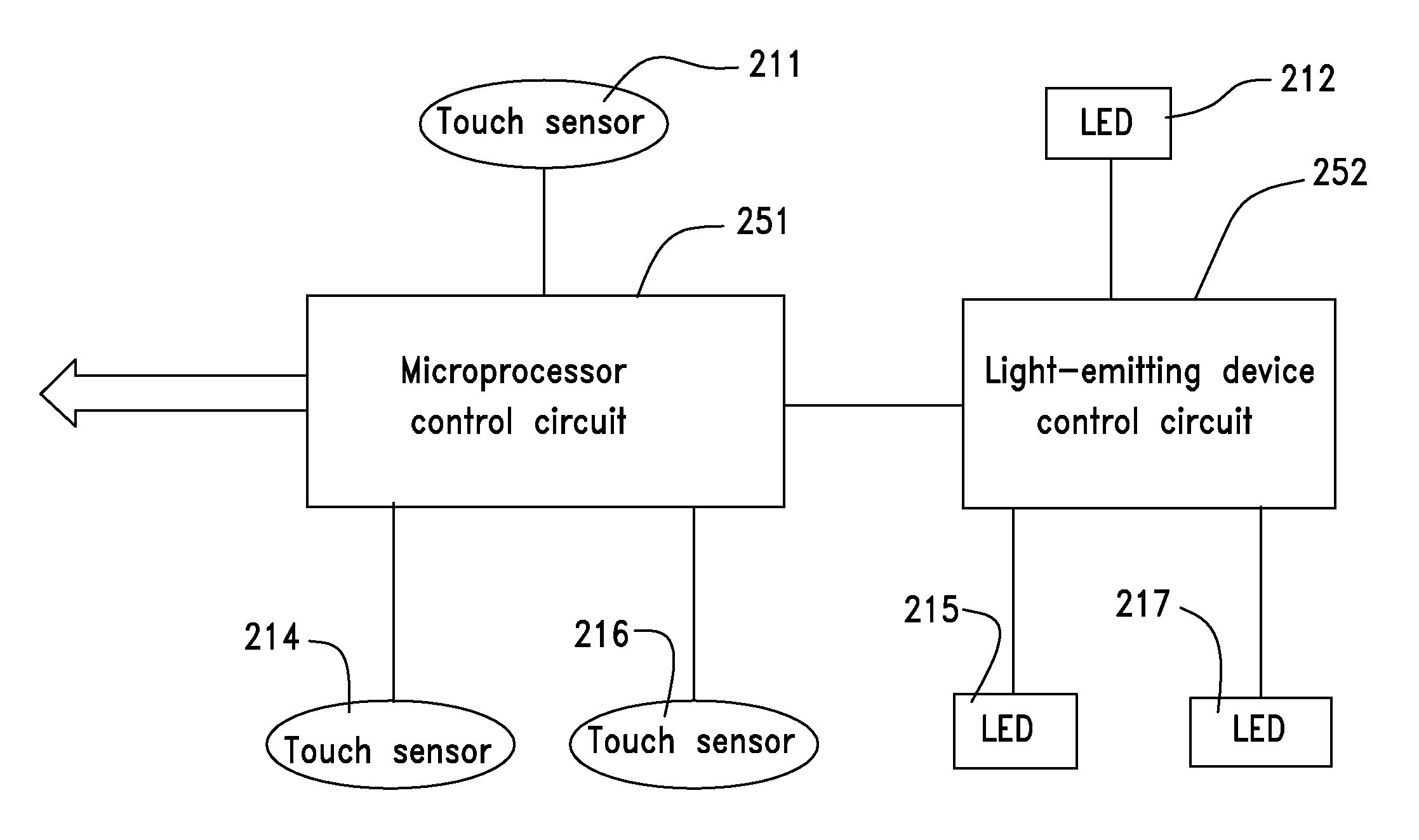
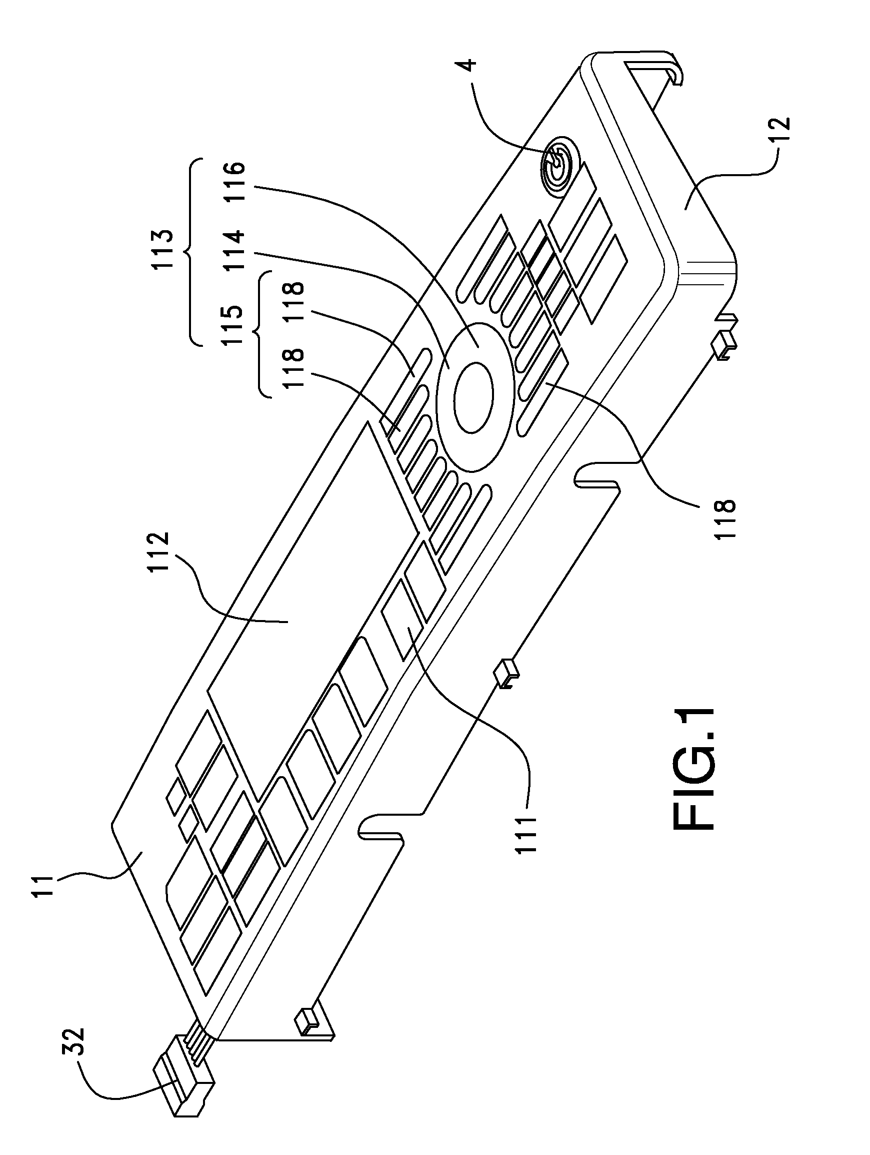
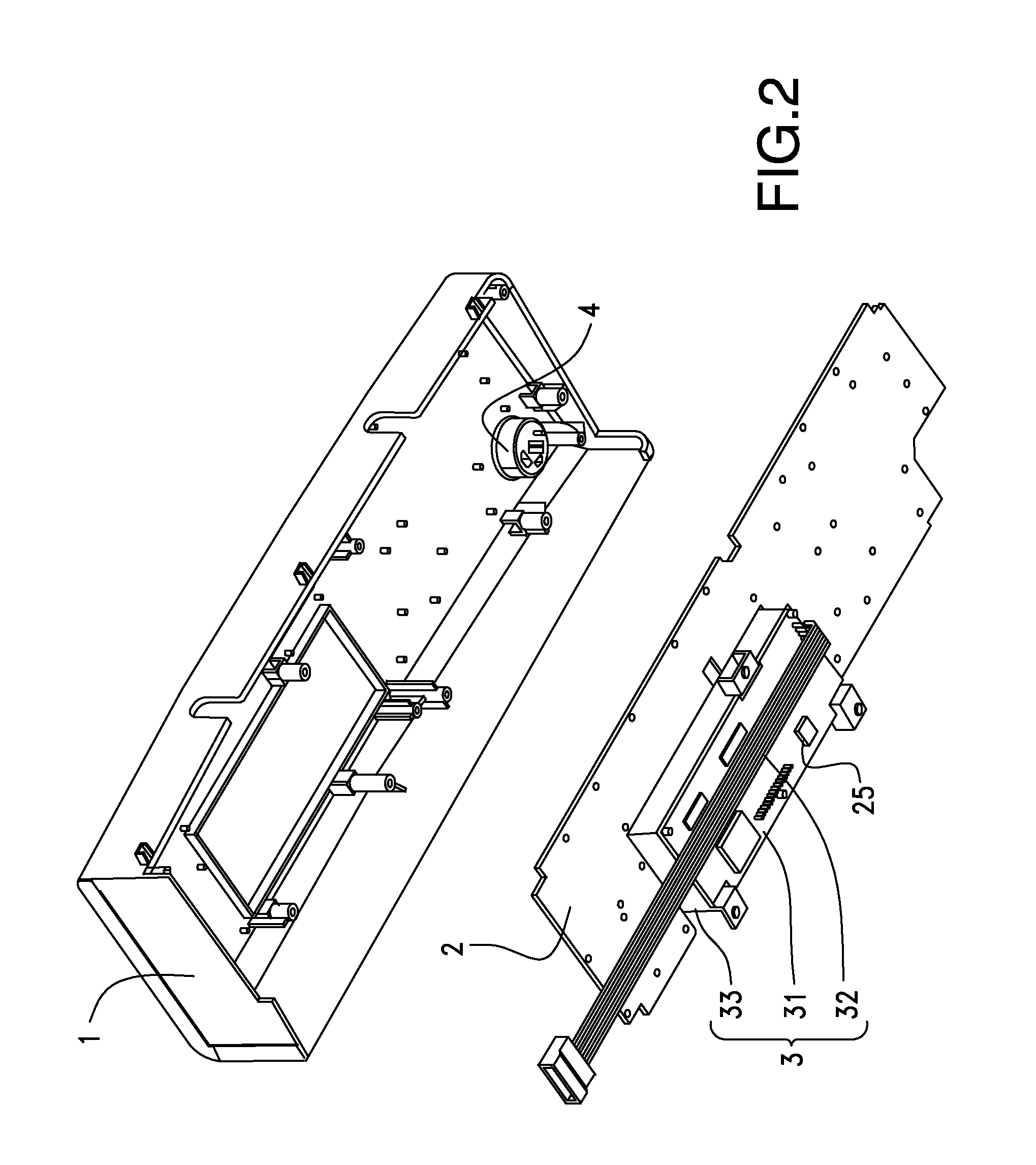
[0007]In light thereof, the Present Disclosure provides a touch panel, comprising a main panel and a light-emitting touch module disposed underneath. The main panel is provided with a plurality of display patterns thereon. A light-emitting touch module includes a first circuit board provided with a plurality of touch sensors, a plurality of light-emitting devices and a plurality of light guiding parts attached to the side edges of the light-emitting devices so as to evenly project the light emitted from the light-emitting devices upward to the display patterns. The light-emitting touch module further comprises a light reflecting part disposed underneath the light guiding parts capable of reflecting the light emitted from the bottom surface of the light guiding parts back to the light guiding parts, which is further projected upward from the display patterns so as to improve the brightness of the patterns.
[0008]The light reflecting part may comprise a layer of light reflecting film printed with a light reflecting ink on the first circuit board, which is attached underneath the bottom surface of the light guiding parts. The touch sensors may be capacitive touch sensors, and the light reflecting film can be directly printed above the touch sensors. The light-emitting touch module may comprises a spacer disposed between the main panel and a first circuit board, the spacer being made of an opaque material, and holding holes that run through vertically are formed thereon spacer at positions corresponding to the display patterns on the main panel for correspondingly holding the light guiding parts. Preferably, the top surface of the light guiding parts is a rough cloudy surface, while the bottom surface thereof is a smooth surface. The light-emitting touch module may further comprise a second circuit board and a touch control circuit disposed thereon, the second circuit board being electrically connected to the first circuit board, spaced apart from the first circuit board at a distance so as to reduce the electromagnetic interference by the touch control circuit on the touch sensors. The light-emitting touch module may further comprise a display module disposed at one side of the first circuit board side by side. The second circuit board may be disposed on the bottom surface of the display module, while electronic components that form the touch control circuit are disposed on the bottom surface of the second circuit board that is away from the main panel.

Problems solved by technology

The light intensity of the light-emitting device, however, has to be increased to ensure that the display patterns have the pre-set brightness, which increases the power consumption and is harmful to energy saving and environmental protection.

Method used


Image

  • Touch Panel
  • Touch Panel
  • Touch Panel

Examples


Embodiment Construction

[0024]While the Present Disclosure may be susceptible to embodiment in different forms, there is shown in the Figures, and will be described herein in detail, specific embodiments, with the understanding that the disclosure is to be considered an exemplification of the principles of the Present Disclosure, and is not intended to limit the Present Disclosure to that as illustrated.

[0025]As such, references to a feature or aspect are intended to describe a feature or aspect of an example of the Present Disclosure, not to imply that every embodiment thereof must have the described feature or aspect. Furthermore, it should be noted that the description illustrates a number of features. While certain features have been combined together to illustrate potential system designs, those features may also be used in other combinations not expressly disclosed. Thus, the depicted combinations are not intended to be limiting, unless otherwise noted.

[0026]In the embodiments illustrated in the Figu...


PUM


Abstract

The Present Disclosure provides a touch panel, comprising a main panel and a light-emitting touch module disposed underneath. The main panel is provided with a plurality of display patterns thereon. A light-emitting touch module includes a first circuit board provided with a plurality of touch sensors, a plurality of light-emitting devices and a plurality of light guiding parts attached to the side edges of the light-emitting devices so as to evenly project the light emitted from the light-emitting devices upward to the display patterns. The light-emitting touch module further comprises a light reflecting part disposed underneath the light guiding parts capable of reflecting the light emitted from the bottom surface of the light guiding parts back to the light guiding parts, which is further projected upward from the display patterns so as to improve the brightness of the patterns.

Description

REFERENCE TO RELATED APPLICATIONS[0001]The Present Disclosure claims priority to prior-filed Chinese Utility Model Patent Application No. 201120149330, entitled “Touch Panel,” filed on 6 May 2011 with the State Intellectual Property Office of the People's Republic of China; Chinese Patent Application No. 201110121528.0, entitled “Touch Panel,” filed on 6 May 2011 with the State Intellectual Property Office of the People's Republic of China; and Chinese Patent Application No. 201110121517.2, entitled “Touch Panel,” filed on 6 May 2011 with the State Intellectual Property Office of the People's Republic of China. Additionally, the Present Disclosure is related to Taiwanese Utility Model Patent Application No. 100210368, entitled “Touch Panel,” filed on 8 Jun. 2011 with the Intellectual Property Office of the Republic of China; Taiwanese Patent Application No. 10119966, entitled “Touch Panel,” filed on 8 Jun. 2011 with the Intellectual Property Office of the Republic of China; and Taiw...

Claims


Application Information

Patent Timeline
IPC IPC(8): G06F3/041G06F3/044
CPCG06F3/044G06F3/0412H01H9/182
Inventor WANG, QIANGZENG, ZHI-HUALI, CHONG-JUNFAN, BING-QUAN
Owner MOLEX INC
Learn More