Display Apparatus

a technology of display device and display device, which is applied in the direction of instruments, casings with display/control units, circuit arrangements on conductive chasms, etc., can solve the problems of limitation in limitation in the slimness of display device and the advance toward new design, etc., to enhance the sense of beauty in design, the effect of minimizing thickness

Active Publication Date: 2012-11-08
LG DISPLAY CO LTD
View PDF9 Cites 89 Cited by
  • Summary
  • Abstract
  • Description
  • Claims
  • Application Information

AI Technical Summary

Benefits of technology

[0010]An aspect of the present invention is to provide a display apparatus that minimizes thickness and enhances a sense of beauty in design by removing some of case and set covers.
[0011]Another object of the present invention is to provide a display apparatus that prevents a film member combined with an upper substrate of a display panel exposed to the outside for the minimum thickness

Problems solved by technology

In efforts to minimize the thicknesses of LCD devices and design development to enhance a sense of beauty that have been made to date, the existing elements have been applied as is, the structure of the elements has been minimally changed, and therefore, there are limitations in minimizing the thicknesses of the LCD devices and developing new designs of the LCD devices.
As the lower an

Method used


Image

  • Display Apparatus
  • Display Apparatus
  • Display Apparatus

Examples


first embodiment

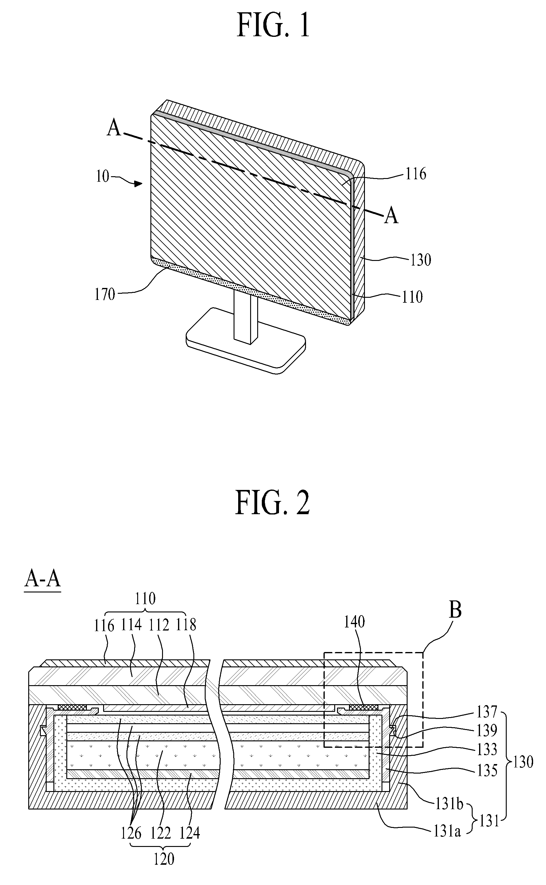
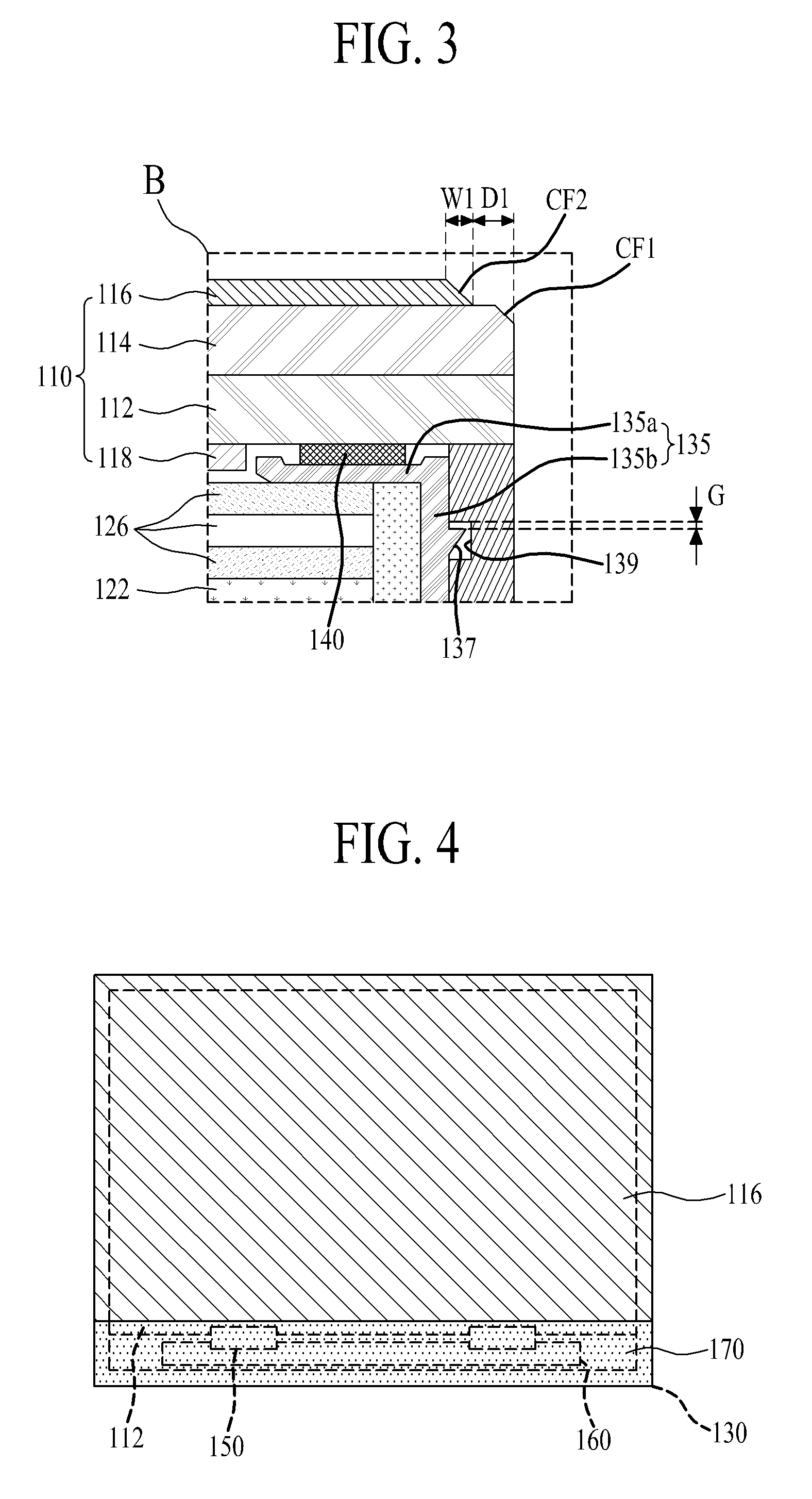
[0058]In the display apparatus 10 according to the first exemplary embodiment, the display panel 110 is combined with the guide frame 135 by the use of adhesive member 140, and the guide frame 135 with the display panel 110 combined therewith is combined with the set cover 131. Thus, the upper case and front set cover of the related art can be eliminated. However, since the display panel 110 is fixed to the guide frame 135 by the adhesive member 140, light leakage may occur due to the change of liquid crystal layer by the external force applied to the display panel 110 to which the adhesive member 140 is attached, or the change of liquid crystal layer by the adhesive strength of the adhesive member 140. That is, the light leakage may occur because the display panel 110 is not moved. To solve this problem of light leakage, as shown in FIG. 3, the first coupling member 137 and the second coupling member 139 are coupled with a predetermined gap (G) for the movement of the display panel...

second embodiment

[0061]As shown in FIGS. 5 and 6, the display apparatus 20 includes a display panel 210 for displaying a stereoscopic image, wherein the display panel 210 includes a lower substrate 112, an upper substrate 114 confronting the lower substrate 112, and a film member 216 combined with the upper substrate 114; a backlight unit 120 which emits light toward the display panel 210; a panel support member 130 which receives the backlight unit 120, and supports the display panel 210 to expose the front and lateral sides of the display panel 210 to the outside; and an adhesive member 140 which connects the display panel 210 and the panel support member 130 with each other.

[0062]Except that left and right images are spatially divided by the display panel 210, and are separated by the film member 216, the display apparatus 20 according to the second exemplary embodiment is generally the same in structure to the display apparatus 10 according to the first exemplary embodiment. Thus, a detailed ex...

sixth embodiment

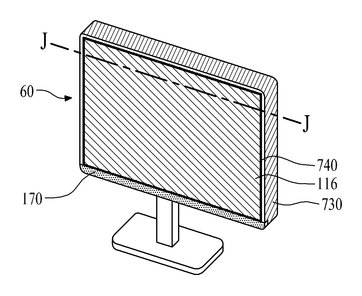
[0104]Like the display apparatus 40 according to the fourth exemplary embodiment, the display panel 110 of the display apparatus 60 may display the stereoscopic image. In the same manner as the film member 216 of the display apparatus 40 according to the fourth exemplary embodiment, the film member 116 of the display apparatus 60 according to the sixth exemplary embodiment also includes the upper polarizing film 216a and the retarder film 216b.

[0105]For the above description, the liquid crystal display product is manufactured by the display apparatus 10, 20, 30, 40, 50, 60 according to the first to sixth exemplary embodiments which include the display panel 110, 210 and the backlight unit 120. However, the display panel 110, 210 of the display apparatus 10, 20, 30, 40, 50, 60 according to the first to sixth exemplary embodiments may be substituted by an organic light emitting display panel including an organic light emitting device. In this case, since the organic light emitting d...


PUM


Abstract

A display apparatus includes a display panel including lower and upper substrates confronting each other, and a film member combined with the upper substrate; and a panel support member to support the display panel to expose the front and lateral sides of the display panel to the outside.

Description

CROSS REFERENCE TO RELATED APPLICATIONS[0001]This application claims the benefit of the Korean Patent Application No. 10-2011-0041296 filed on May 2, 2011, which are hereby incorporated by reference as if fully set forth herein.BACKGROUND OF THE INVENTION[0002]1. Field of the Invention[0003]The present invention relates to a display apparatus, and more particularly, to a display apparatus that minimizes thickness while enhancing a sense of beauty through an innovative design.[0004]2. Discussion of the Related Art[0005]Recently, various flat-type display devices have been actively researched and studied as substitutes for cathode ray tube (CRT) displays. The most widely considered devices include liquid crystal display (LCD) devices, plasma display panel (PDP), field emission display (FED) devices, and light emitting display (LED) devices. The LCD device has attracted especially great attention due to its advantageous properties, such as mass production technology, simple driving mea...

Claims


Application Information

Patent Timeline
IPC IPC(8): H05K7/02G02B30/25
CPCG02F1/133308G02F2001/133311G02F2001/133317G02F2001/13332G02F2001/133331G02F2201/503H05K7/02G02B5/3083G02B27/26H04N13/0434H04N13/0452H04N2213/001H05K5/0017G02F2413/01H04N13/337H04N13/356G02B30/25G02F1/13332G02F1/133311G02F1/133331G02F1/133317
Inventor HWANG, HAK MOKIM, IN JUEYOON, YONG JOONGYOON, SUNG HWANGA, IN-HAN
Owner LG DISPLAY CO LTD
Why Eureka
Try Eureka