Filtering Device

Inactive Publication Date: 2012-11-08
PASSLER KARLHEINZ
View PDF4 Cites 3 Cited by
  • Summary
  • Abstract
  • Description
  • Claims
  • Application Information

AI Technical Summary

Benefits of technology

[0008]In contrast to this, the present invention has the task of creating a filtering device making possible a reliable cleaning operation without any addit

Problems solved by technology

For industrial use, such filtering devices are of considerable lengths.
This results in a slightly more even removal of the compression layer, but the pressure wave thus created will cause also catalytic material which is not yet worn out to be catapulted off, such that the resulting losses are too high.
However, this is unfavourable in the process because such entrances are then easily polluted by the compression layer sliding downwards, and

Method used


Image

  • Filtering Device
  • Filtering Device
  • Filtering Device

Examples


Example

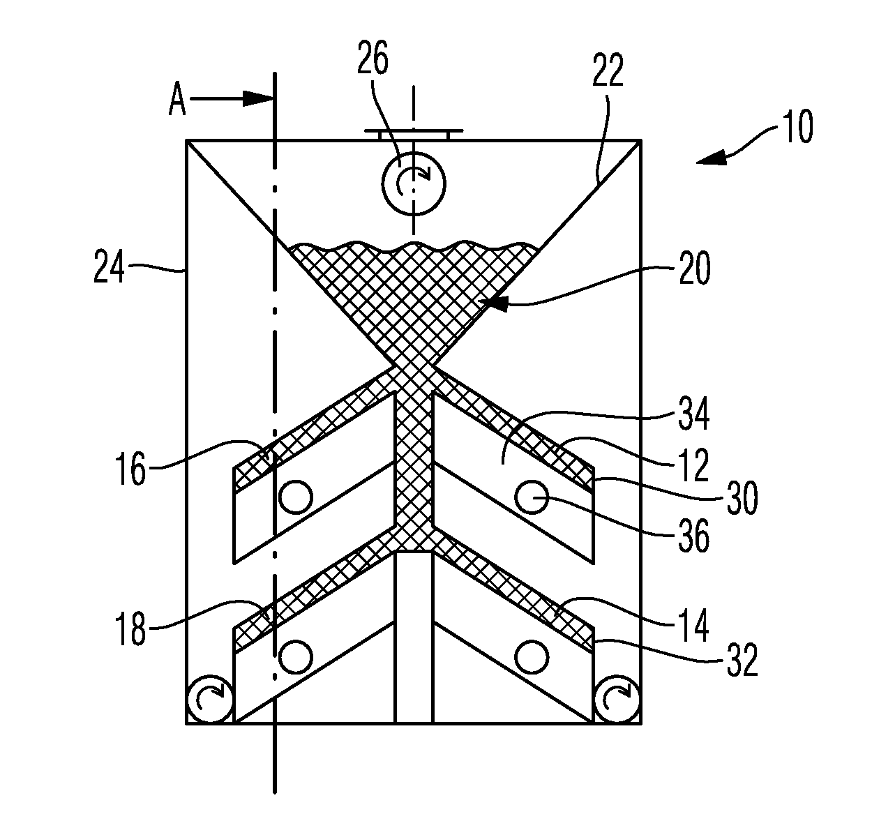
[0039]The embodiment of a filtering device 10 in accordance with the present invention depicted in FIG. 1 has several inclined beds 12, 14, 16 and 18 which extend in a firtree-like fashion in the exemplary embodiment shown. A filling 20 made up of catalytic material is provided which is supplied in a uniform fashion in an insertion hopper 22 along the length of filter box 24. For this purpose, the individual hopper 22 is provided with a dosing screw 26 extending in the longitudinal direction of filter box 24 and serving for the uniform supply of filling 20.

[0040]The catalytic material of filling 20 slides onto beds 12 and 18 in a basically known fashion, with the inclination of the beds corresponding to the filling angle of the catalytic material. At the lower longitudinal side 30 of each bed, a retaining wall 32 is provided, which needs not be formed in a vertical position, but which may for instance also extend horizontally, as can be taken from the above-mentioned disclosure to w...


PUM

PropertyMeasurementUnit
Temperatureaaaaaaaaaa

Abstract

The invention relates to a filtering device for multiply polluted gasses, with an inclined bed with a filling of catalytic material, which bed has a retaining wall at its lower longer side, with a clean-gas exit positioned in the area of one front side of the bed, which ejects the gas which has passed through the filling, and with a flush-gas entrance also positioned in the area of one front side of the bed, the flush-gas entrance (40) and the clean-gas exit (36) being provided at the same front side (38), and beneath the bed (12), current-influencing devices (50) being positioned spread between the two front sides, which devices prevent or at least reduce current peaks in the flow of flush gas through the bed (12).

Description

TECHNICAL FIELD[0001]The invention relates to a filtering devicefor multiply polluted gasses, with an inclined bed with a filling of catalytic material, which bed has a retaining wall at its lower longer side, with a clean-gas exit positioned in the area of one front side of the bed, which ejects the gas which has passed through the filling, and with a flush-gas entrance also positioned in the area of one front side of the bed.BACKGROUND OF THE INVENTION[0002]Such a filtering device is known for instance from DE 10 2005 022 138 A1. This filtering device is characterized in that it is particularly suited for filtering out dust, dioxins, nitrogen oxides or the like, in particular from blast-furnace waste gasses or waste-incinerating plants. For this purpose, it has a number of inclined beds which are provided with a filling of catalytic material. At the lower longer side of the bed, the catalytic material borders a retaining wall each, and the bed is penetrated by a flow or current fr...

Claims


Application Information

Patent Timeline
IPC IPC(8): B01D53/86B01D53/72B01D53/56
CPCB01D46/0068B01J2208/00849B01D46/34B01D53/0446B01D53/8603B01D53/8625B01D53/8662B01D53/885B01D2255/20723B01D2257/20B01D2257/30B01D2257/404B01D2259/4591B01J8/002B01J8/003B01J8/0035B01J8/0045B01J8/0242B01J2208/00752B01J2208/00761B01D46/30B01D46/71
Inventor PASSLER, KARLHEINZ
Owner PASSLER KARLHEINZ
Why Eureka
Try Eureka