Fabrication of alloy variant structures using direct metal deposition

Inactive Publication Date: 2005-10-13
DM3D TECH
View PDF30 Cites 4 Cited by
  • Summary
  • Abstract
  • Description
  • Claims
  • Application Information

AI Technical Summary

Benefits of technology

[0016] In the preferred embodiment, the invention uses DMD to deposit a first material or alloy in an area exposed to high wear, such as the tooling gate area, with a second material or alloy being used elsewhere in the tool for greater impact resistance. Advantageously, the areas may be of a user-defined thickness to furth

Problems solved by technology

In manufacturing, a critical, time-limiting step for many products is the design and fabrication of “tooling,” including molds and dies.
In many cases, the application requirements within a mold or die component differ, resulting in a reduction in die life requiring repair or replacement of the die or mold.
Each section or mold component is fabricated from a homogenous metal alloy, which results in homogenous material properties within each die or mold component.
The variation in material property requirements within a mold or die component, results in localized wear or and premature failure of the mold or die component in the are

Method used


Image

  • Fabrication of alloy variant structures using direct metal deposition
  • Fabrication of alloy variant structures using direct metal deposition
  • Fabrication of alloy variant structures using direct metal deposition

Examples


Example

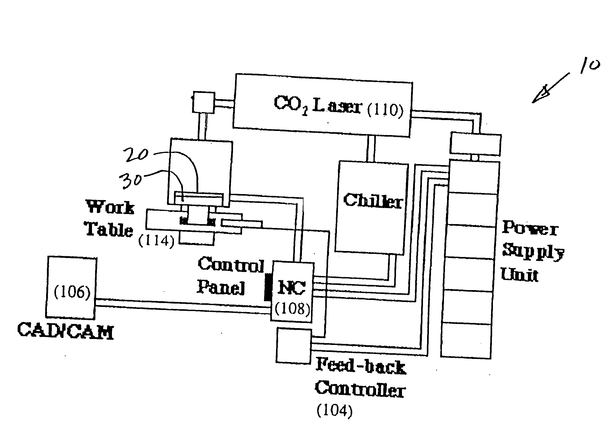
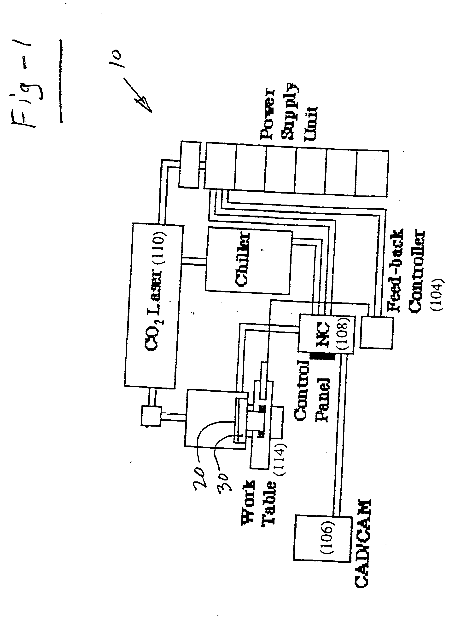
[0019]FIG. 1 illustrates a laser-aided, computer controlled direct material deposition (DMD) system in schematic form. The system 10 applies layers of material 20 on a substrate 30 to fabricate an object or cladding. As discussed above, the system is preferably equipped with feedback monitoring to control of the dimensions and overall geometry of the fabricated article. The geometry of the article is provided by a computer-aided design (CAD) system.

[0020] The deposition tool path is generated by a computer-aided manufacturing (CAM) system for CNC machining with post-processing software for deposition, instead of software for removal as in conventional CNC machining. CAM software interfaces with a feedback controller 104. These details of the laser-aided, computer controlled direct material deposition system are disclosed in U.S. Pat. No. 6,122,564, and are therefore not all explicitly shown in FIG. 1.

[0021] The factors that affect the dimensions of material deposition include lase...


PUM

PropertyMeasurementUnit
Thicknessaaaaaaaaaa
Wear resistanceaaaaaaaaaa
Structureaaaaaaaaaa

Abstract

Direct-metal deposition (DMD), preferably under closed-loop control, is used to fabricate alloy-variant material structures which provide a combination of desirable physical and mechanical properties. Use of the invention facilitates the production of high-strength, high-wear, and impact-resistant structures which decrease the likelihood of erosion, heat checking and brittle failure in injection molds, die casting, thixomolding and other, more exotic tooling. The invention uses DMD to deposit a first material or alloy in an area exposed to high wear, such as the tooling gate area, with a second material or alloy being used elsewhere in the tool for greater impact resistance. Advantageously, the areas may be of a user-defined thickness to further improve longevity. The resulting composite material structure has mechanical properties (i.e., yield strength, hardness and abrasion resistance) which exceed that of the homogeneous compositions currently used for mold materials, thereby enhancing productivity while improving part quality in these and other applications.

Description

REFERENCE TO RELATED APPLICATION [0001] This application claims priority of U.S. provisional patent application Ser. No. 60 / 202,590, filed May 9, 2000, and is a continuation-in-part of U.S. patent application Ser. No. 09 / 670,670, filed Sep. 27, 2000, the entire contents of each application being incorporated herein by reference.FIELD OF THE INVENTION [0002] This invention relates generally to additive manufacturing processes and, in particular, to the formation of alloy variant structures using laser-assisted direct metal deposition (DMD) processes. BACKGROUND OF THE INVENTION [0003] In manufacturing, a critical, time-limiting step for many products is the design and fabrication of “tooling,” including molds and dies. Complex dies may take from weeks to a year to perfect prior to manufacture of a product. In present manufacturing processes, added steps are necessary to overcome existing fabrication methods. For example, molds and dies must be machined to provide cooling channels and...

Claims


Application Information

Patent Timeline
IPC IPC(8): B22D23/00B23K26/34B29C33/38B29C45/27B29C45/37C23C4/00C23C4/02C23C4/12C23C24/10C23C26/02
CPCB29C33/38B29C45/2708B29C45/37C23C4/00C23C4/02C23C4/12C23C24/10C23C26/02C23C4/01B22C3/00
Inventor SKSZEK, TIMOTHY W.LOWNEY, MATHEW T.J.MORGAN, DWIGHT
Owner DM3D TECH
Why Eureka
Try Eureka