Heated Compression Therapy System and Method

a compression therapy and heating technology, applied in the field of heated compression therapy system and method, can solve the problems of body temperature drop, loss of ability to regulate temperature of anesthetized patients undergoing surgery, severe complications, etc., to reduce the chance of shock to patients, eliminate the risk of electrical shock and connection wires, and cost

Active Publication Date: 2012-11-08
BATRA MUNISH K +1
View PDF20 Cites 3 Cited by
  • Summary
  • Abstract
  • Description
  • Claims
  • Application Information

AI Technical Summary

Benefits of technology

[0011]Although not essential, it is advantageous to use a low, direct current voltage to energize the heating pad. This is advantageous because conventional 60 hertz AC power can interfere with the body's nervous and cardio vascular systems. It is also advantageous (but not essential) to provide electrical energy from a battery. This is advantageous because the battery / heating pad system is electrically isolated thus reducing the chance of shocking the patient.
[0012]The air-activated heat pack fits inside of the air bladder and is activated and heated as pressurized air is intermittently applied. Air-activated heat packs are known in the art. A popular variety utilizes iron, water, cellulose, vermiculite, activated carbon, and salt. An example of such a heat pack is the “Grabber” (trademark) brand (www.warmers.com). These heat packs are nicely applied to conventional DVT therapy systems that utilize pressurized air (e.g. intermittent (pulsed) compression systems). The air delivery of these systems serves an additional purpose. Exposure to the pressurized air causes the heat pack to heat up without the need for externally (e.g. electrical pad, heated fluid) generated heat. This offers several advantages including eliminating the risk of electrical shock and connection wires, and also cost effectiveness.
[0013]The present invention incorporates air-activated heat packs with conventional pressurized air DVT therapy systems to provide a cost effective, efficient means of adding heat to pressurized therapy. The heat packs are contained within the air bladder (aka internal chamber) of the calf garment. The combination must be stored, until just prior to use, in an air-tight package to prevent premature activation.

Problems solved by technology

This can result in severe complications—including death.
The body of an anesthetized person undergoing surgery loses the ability to regulate temperature because the body is paralyzed.
Thus, body temperature drops as a result.
This drop in temperature increases the risk of DVT and increases post-operative recovery time (i.e. length of time outpatient must wait before being released).
Such solutions are problematic because the blanket and interconnecting hoses are relatively large and cumbersome and tend to interfere with the surgeon needing access to various parts of the body.
Additionally, the large, inefficient apparatus used to heat and deliver pressurized air wastes heat that results in a detrimental increase in room temperature.
However, such systems are inefficient because the heat must be transferred to the fluid, then delivered to the bladder, then transferred from the bladder to the calf.

Method used


Image

  • Heated Compression Therapy System and Method
  • Heated Compression Therapy System and Method
  • Heated Compression Therapy System and Method

Examples


Embodiment Construction

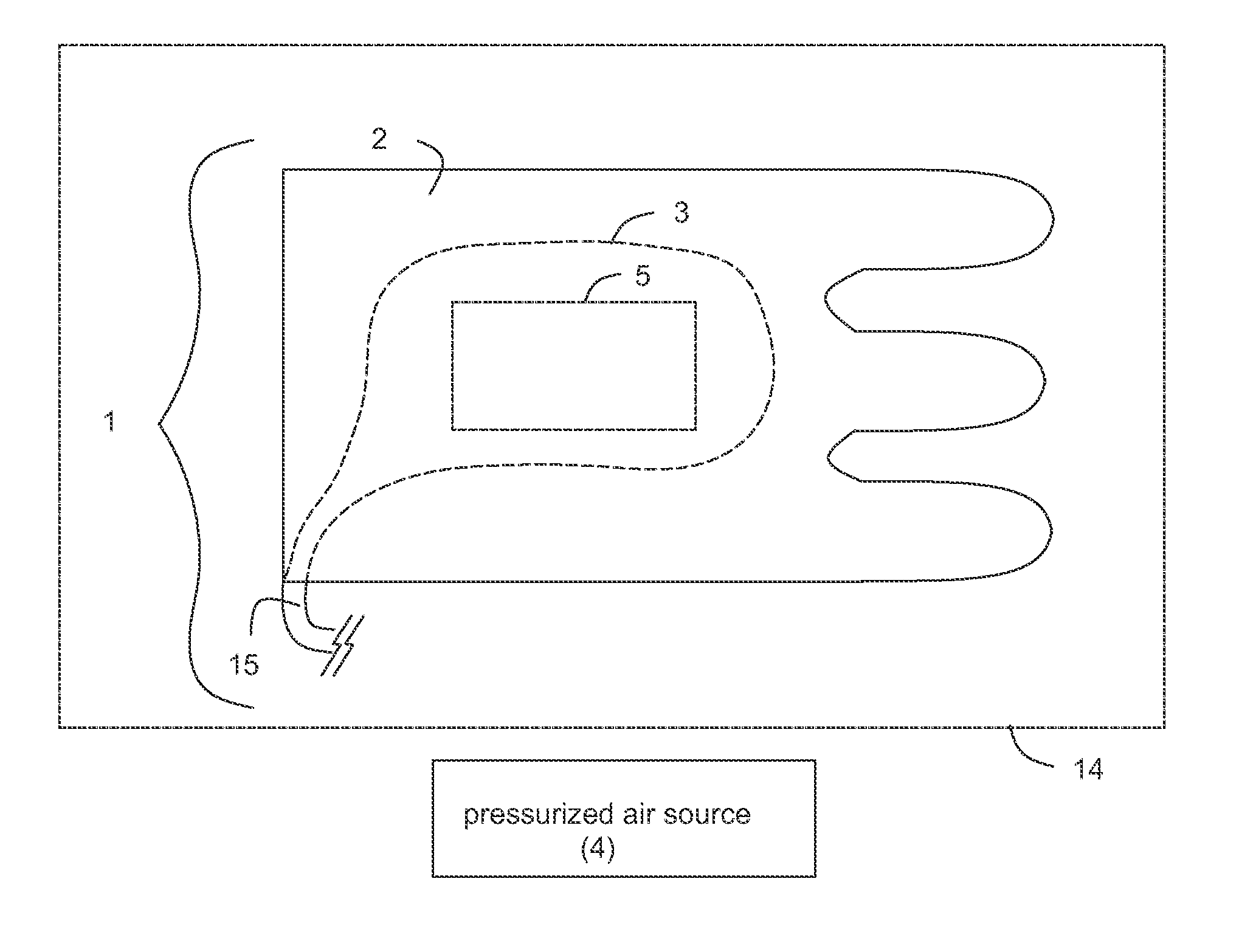
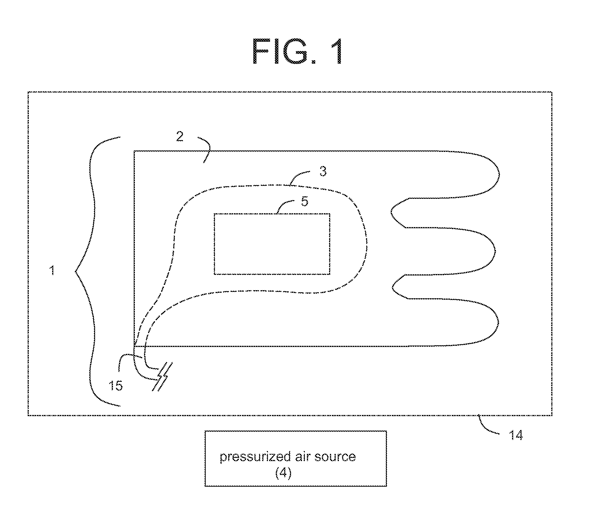
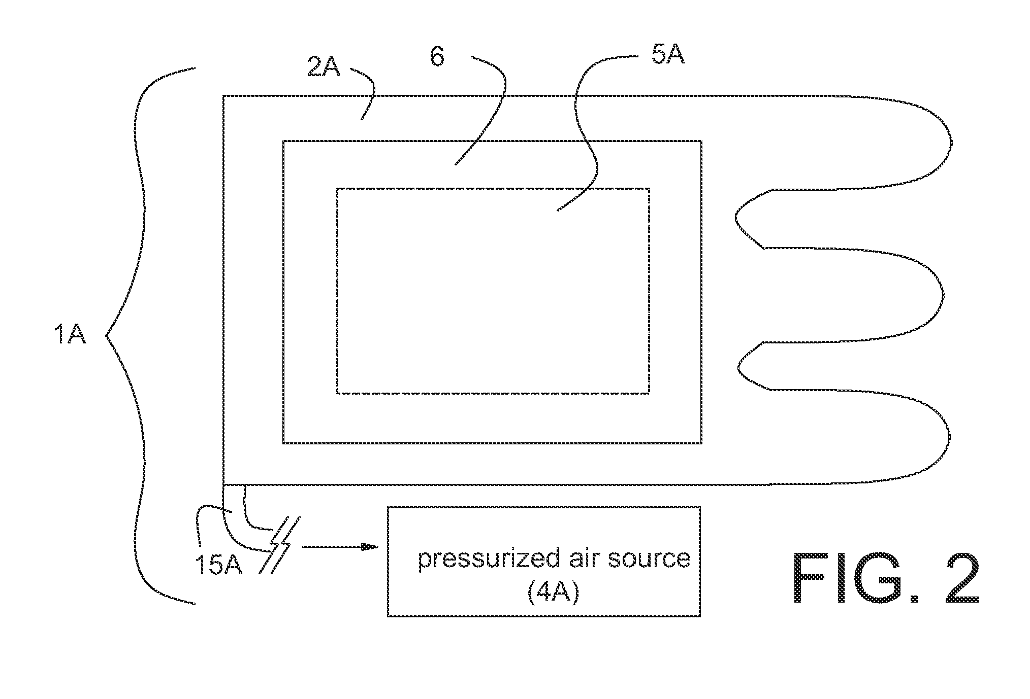
[0019]In various embodiments, a calf garment assembly 1, 1A comprises, calf garment 2, 2A having internal chamber 3, 3A being substantially airtight and being in fluid communication with pressurized air source 4, 4A, and heating element 5, 5A being restrained proximate calf garment 2, 2A, respectively.

[0020]Referring now to FIG. 1, heating element 5 can be either securedley attached within internal chamber 3, or alternatively can be loosely inserted within. If the latter, the positioning of heating element 5 can vary relative to a patient's leg while in use. Fixing the heating pad within internal chamber 3 allows a more predictable result.

[0021]In operation, calf garment assembly 1 is sealed in airtight package 14, to ensure heating element 5 (air-activated heat pack) is not activated by premature exposure to air. Calf garment assembly 1 is removed from airtight package 14 just prior to use. Port 15 of internal chamber 3 of calf garment 2 is connected to pressurized air source 4. Ca...


PUM


Abstract

A calf garment assembly comprises, a calf garment having an internal chamber and being substantially airtight and being in fluid communication with a pressurized air source, and a heating element working in conjunction with the calf garment to provide heated DVT therapy.

Description

[0001]The present application is related to the co-pending provisional patent application No. 61 / 385,810 of Munish K. Batra, et al, filed on Sep. 23, 2010, entitled “Heated Compression Therapy System and Method”, and based on which priority is herewith claimed under 35 U.S.C. 119(e) and the disclosure of which is incorporated herein by reference in its entirety as if fully rewritten herein.BACKGROUND AND SUMMARY[0002]The present invention relates generally to systems and methods for minimizing or preventing deep vein thrombosis (DVT) and maintaining the body temperature of a person under anesthesia, and specifically to systems and methods that incorporate applying heat and compression in furtherance thereof.[0003]Deep vein thrombosis (DVT) relates to the forming of blood clots (thrombi) in the deep veins of the body, usually in the pelvis, thigh, or calf. This can result in severe complications—including death. One of the causes of DVT is surgery. The body of an anesthetized person ...

Claims


Application Information

Patent Timeline
Patent Type & Authority Applications(United States)
IPC IPC(8): A61H1/00
CPCA61F7/007A61F2007/0288A61F2007/0091A61H9/0078A61H9/0092A61H2201/0107A61H2201/0207A61H2201/0228A61H2201/0278A61H2201/5082A61H2209/00Y10S601/02A61F7/02A61F2007/0043A61F2007/0086A61F7/08
Inventor BATRA, MUNISH K.KOCH, RONALD J.
Owner BATRA MUNISH K
Why Eureka
Try Eureka