Interbody fusion device

a fusion device and implant technology, applied in the field of implants for orthopedic surgery, can solve the problems of affecting the blood supply of patients' vertebrae, affecting affecting the patient's blood supply, so as to improve the stability of the u-shaped plate, prevent collapse or fracture, and facilitate the formation of biological connections

Inactive Publication Date: 2012-11-08
DING ZHENQI +1
View PDF6 Cites 0 Cited by
  • Summary
  • Abstract
  • Description
  • Claims
  • Application Information

AI Technical Summary

Benefits of technology

[0004]The object of the present invention is to provide interbody fusion device, which could prevent the disadvantages of the titanium cage.
[0008]The upper ends and lower ends of the back wall, front wall and the bottom of the U-shaped plate are configured with flanges. The flanges produce friction between the U-shaped plate and the caudad endplate of the upper vertebral body and the cephalad endplate of the lower one, which improves the stability of the U-shaped plate.
[0009]The upper and the lower ends of the U-shaped plate is configured parallel to each other or not. The upper and the lower ends of the U-shaped plate parallel to each other makes it more fit to the thoracic vertebrae end-plate; the upper and the lower ends of the U-shaped plate unparallel to each other makes it more fit to the lumbar vertebrae end-plate; they could prevent collapse or fracture of the upper and the lower lumbar vertebrae due to the partial pressure.
[0010]The present invention of interbody fusion device (it could be also called U-shaped artificial vertebrae) comprises a titanium alloy U-shaped plate of 0.6 cm and two screws locking the U-shaped plate between the caudad endplate of the upper vertebral body and the cephalad endplate of the lower one. The inner and the front of the U-shaped plate could be implanted with large amount of bone graft, making it easily to form biological connection. Corpectomy or the total removal of the damaged vertebral body is not needed and only one-third of posterior part of vertebral body is removed because of the small volume of the U-shaped plate. It keeps the anterior column and part of middle column of the damaged vertebral body. It retains most of the vertebrae bone, which reduces blooding and supports the vertebrae blood supply, beneficial to the interbody fusion of the anterior-middle column of the damaged vertebrae. The back wall of the U-shaped plate serving as a gate is disposed without holes, which prevent the entry of the bone graft to the vertebrae canal and the compression to the nerve structures. The front wall of the U-shaped plate is disposed with holes, making it easier for the biological connecting. The minute vessel grows accompanying with the bone by the holes. The inclined holes at the upper and the lower end of the bottom of the U-shaped plate are disposed with screws inside, the screws lock to the caudad endplate of the upper vertebral body and the cephalad endplate of the lower one, preventing the collapse of the implant. The interbody fusion situation could be direct evaluated by the observing the healing of the front two-third vertebrae when taking imaging examination.

Problems solved by technology

To implant the bulky size of cylindrical titanium cage, corpectomy or the total removal of the damaged vertebral body needs to be done, the patient will blood much and it will damage the blood supply to the vertebrae.

Method used


Image

  • Interbody fusion device
  • Interbody fusion device
  • Interbody fusion device

Examples


first embodiment

The First Embodiment

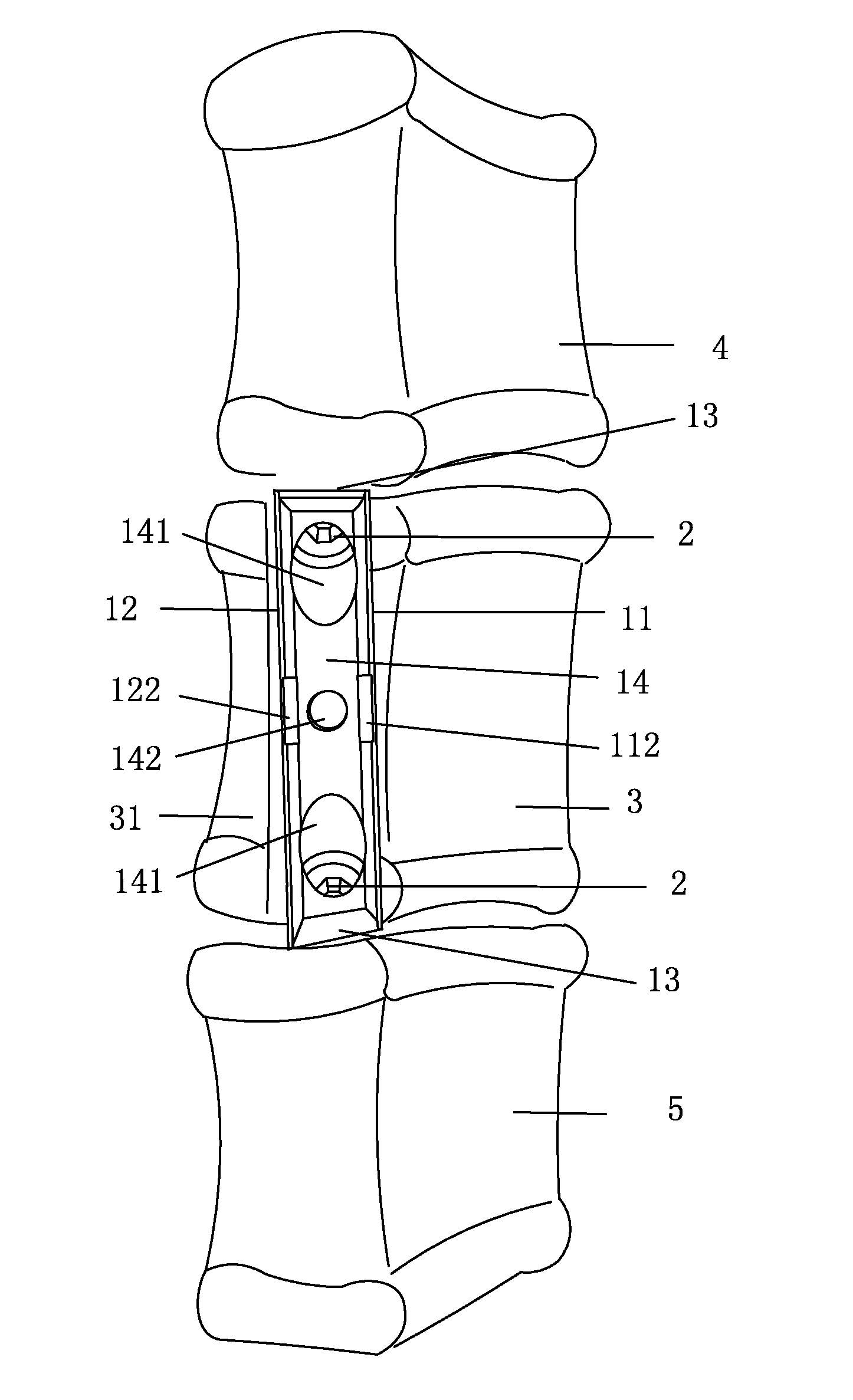
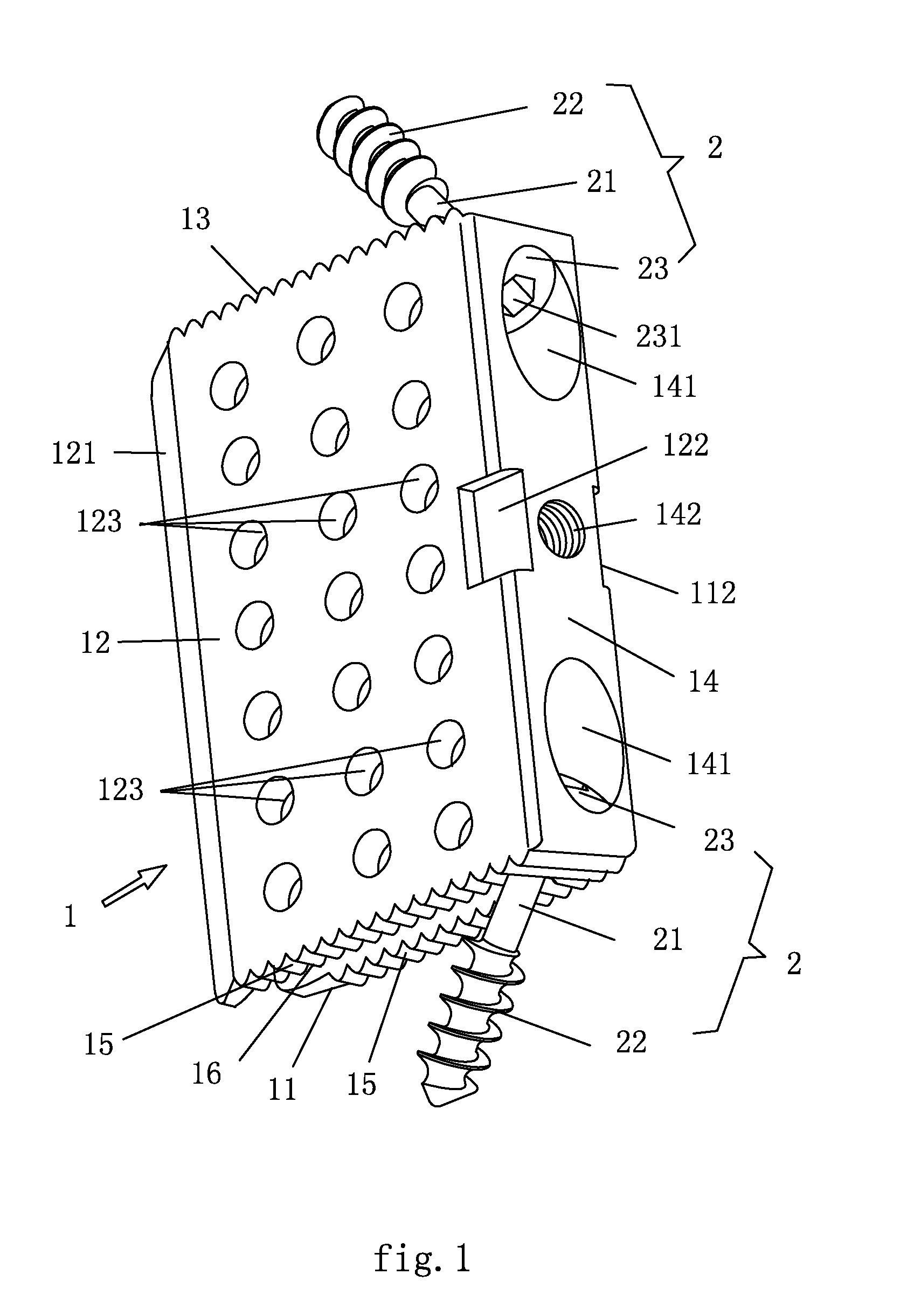
[0022]The object of the present invention is to provide a preferred embodiment of fusion device for vertebral body. The FIG. 1 illustrates the structure of the first embodiment; it comprises a U-shaped plate 1 and two screws 2.

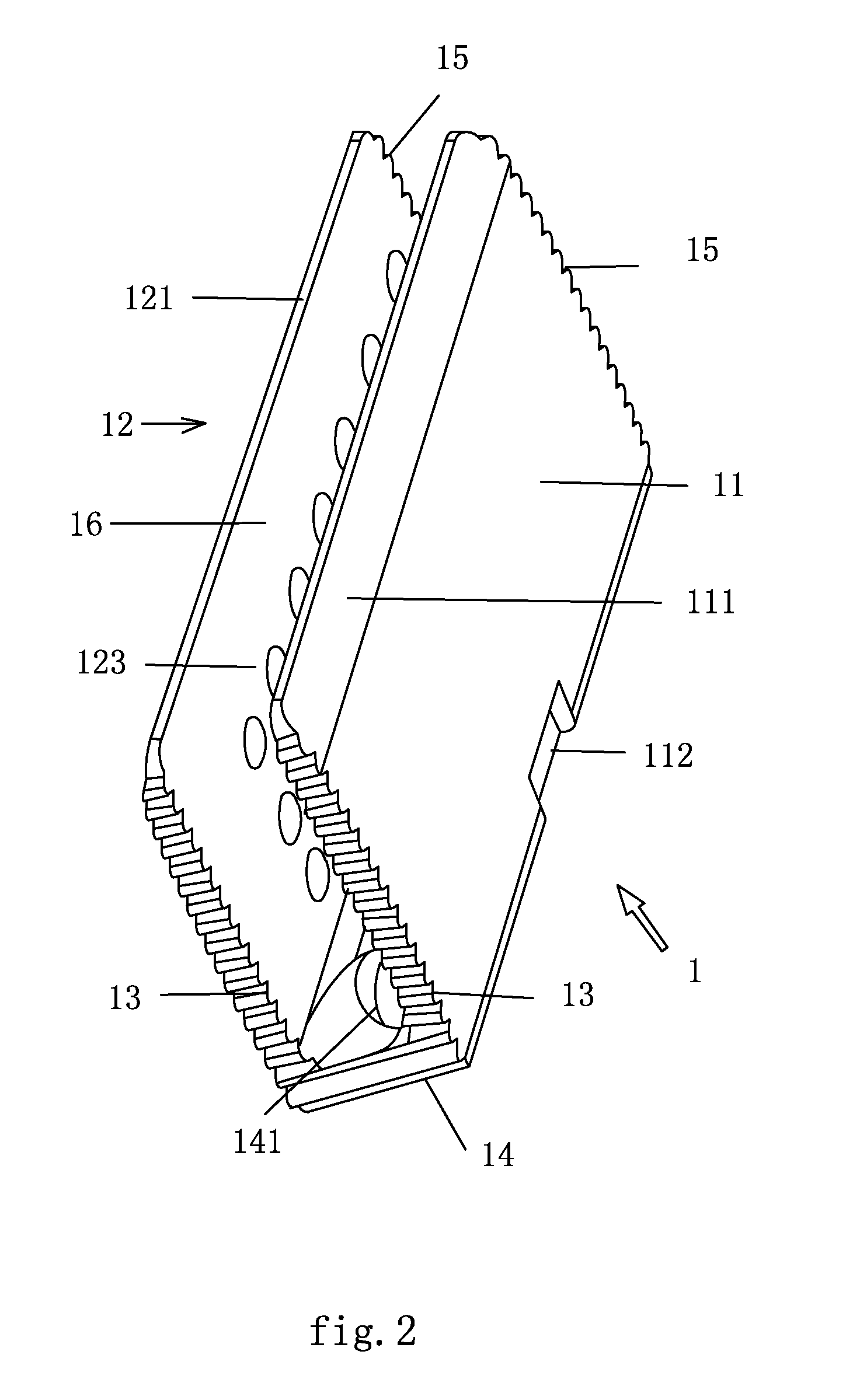
[0023]The U-shaped plate 1 is hollow skeleton made of titanium alloys with thickness of 0.6 cm. FIG. 2 illustrates the structure of the U-shaped plate. The back wall 11 of the U-shaped plate 1 connects to the front wall 12 by the bottom 14. The upper end and the lower end of the U-shaped plate 1 are disposed unparallel to each other and configured with included angle of slope. The upper ends of the back wall 11, front wall 12 and the bottom 14 are configured with flanges 13. The lower ends of the back wall 11, the front wall 12 and the bottom 14 are configured with flanges 15. The back wall 11, the front wall 12 and the bottom 14 are circling around forming the inside groove 16.

[0024]The outer surface of the back wall 11 of the U-shaped pla...

second embodiment

The Second Embodiment

[0031]The present invention provides with the second embodiment of the interbody fusion device for the thoracic vertebral body. FIG. 7 illustrates the structure of the second embodiment, which comprises of a U-shaped plate 6 and two screws 2. The structure of the screws 2 is the same with that of the first embodiment.

[0032]The U-shaped plate 6 is hollow skeleton made of titanium alloys with thickness of 0.6 cm. FIG. 8 illustrates the structure of the U-shaped plate. The back wall 61 of the U-shaped plate 6 connects to the front wall 62 by the bottom 64. The upper end and the lower end of the U-shaped plate 6 are disposed parallel to each other and configured with included angle of slope, which makes it more fit to the thoracic vertebrae end-plate. The upper ends of the back wall 61, front wall 62 and the bottom 64 are configured with flanges 63. The back wall 61, the front wall 62 and the bottom 64 are circling around forming the inside groove 65.

[0033]The outer...


PUM


Abstract

An interbody fusion device related to implants for orthopedic surgery has a hollow skeleton made of titanium alloy to hold nonstructural cancellous bone graft. The skeleton is a U-shaped plate, whose front wall is disposed with holes. The upper and the lower end of the bottom of the U-shaped plate have inclined holes of ladder shape. The bigger end of the inclined hole is placed on the bottom surface of the bottom of the U-shaped plate, and the smaller end of the inclined hole is placed on the corresponding surface of the bottom of the U-shaped plate; the inclined hole of the U-shaped plate is disposed with screw inside. The present invention has small volume and the vertebra is partial removal, so it is more reliable for interbody fusion.

Description

FIELD OF THE INVENTION[0001]The present invention relates to an implant for orthopedic surgery.BACKGROUND OF THE INVENTION[0002]To repair the damaged vertebrae, artificial vertebral body is come out in the medical community aboard, such as titanium cage (TMC). The titanium cage is a hollow skeleton made of titanium alloy formed by titanium alloy plate of several meshes and set in a circle, the inner of the titanium cage is disposed with ring-shaped support. When insert the TMC, the corpectomy or the total removal of the vertebral body needs to be done, and then pack the bone graft in it. The raised spots on the both ends of the titanium cage withstand the cephalad and the caudad endplates separately. With bone growth between vertebral body and bone graft inside the TMC, the fusion of the index level and adjacent vertebral body will be achieved. The minute vessels will grow with the bone graft through the meshes of the titanium cage, achieving the treatment of interbody fusion.[0003]...

Claims


Application Information

Patent Timeline
Patent Type & Authority Applications(United States)
IPC IPC(8): A61F2/44
CPCA61F2/442A61F2310/00023A61F2002/2835A61F2002/30153A61F2002/30176A61F2002/30265A61F2002/30266A61F2002/30271A61F2002/30281A61F2002/30578A61F2002/30736A61F2002/30774A61F2002/30777A61F2002/30779A61F2002/30785A61F2002/30787A61F2002/3082A61F2002/30827A61F2/447A61F2002/30261A61F2002/30593
Inventor DING, ZHENQI
Owner DING ZHENQI
Why Eureka
Try Eureka