
Solar cell module

a solar cell module and solar cell technology, applied in the field of solar cell modules, can solve the problems of insufficient mechanical strength of the side of the frame (frame body) located on the lower side of the solar cell module when it is obliquely placed, and difficulty in discharge of water

Inactive Publication Date: 2012-11-15
SANYO ELECTRIC CO LTD
View PDF1 Cites 6 Cited by
  • Summary
  • Abstract
  • Description
  • Claims
  • Application Information

AI Technical Summary

Benefits of technology

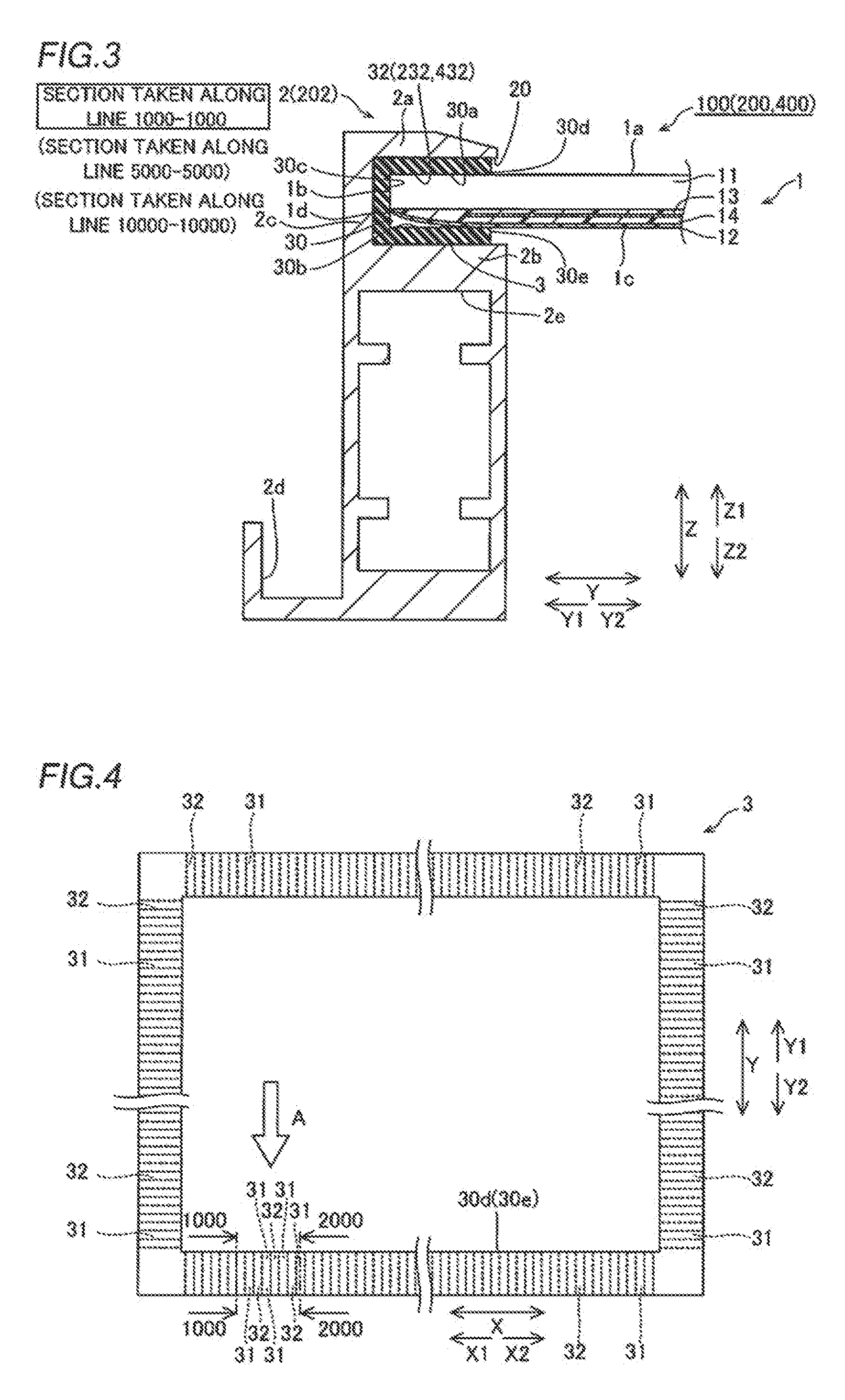
[0012]In the solar cell module according to the aspect of the present invention, as hereinabove described, the groove to discharge the water retained on the upper surface of the solar cell panel is formed in the gasket, whereby the water retained on the upper surface of the solar cell panel can be discharged through the groove. Furthermore, it is not necessary to form a flow channel by notching an upper portion of the frame body in order to discharge the water retained on the upper surface of the solar cell panel, and hence the mechanical strength of the frame body can be maintained. Therefore, the water retained on the upper surface of the solar cell panel can be discharged while the mechanical strength of the frame body is maintained.
[0014]In this case, the groove of the gasket preferably extends from the end portion of the gasket closer to the upper surface of the solar cell panel to be substantially orthogonal to the extensional direction of the side surface of the solar cell panel on which the gasket is arranged. According to this structure, the overall length of the groove in which water flows can be reduced as compared with a case where the groove obliquely intersect with the extensional direction of the side surface of the solar cell panel, and hence the water retained on the upper surface of the solar cell panel can be more reliably discharged through the groove.
[0023]In this case, the groove of the gasket is preferably formed to be connected to the hole. According to this structure, the water retained on the upper surface of the solar cell panel can be easily discharged through the groove of the gasket and the hole connected to the groove.
[0026]In the aforementioned solar cell module in which the hole is formed in the gasket, the frame body preferably includes an upper portion located in a region corresponding to the upper surface of the solar cell panel, a lower portion located in a region corresponding to the lower surface of the solar cell panel, and a side surface portion located in a region corresponding to the side surface of the solar cell panel, a discharge hole to discharge water is preferably provided in the side surface portion of the frame body, and the water retained on the upper surface of the solar cell panel is preferably discharged through the groove and the hole of the gasket and the discharge hole of the side surface portion of the frame body. According to this structure, the water discharged to the side of the gasket closer to the frame body through the groove of the gasket and the hole provided in a region of the gasket corresponding to the side surface of the solar cell panel can be discharged to an external portion of the frame body through the discharge hole provided in the side surface portion of the frame body. Furthermore, the discharge hole to discharge the water to the external portion is provided in the side surface portion of the frame body, whereby the mechanical strength of the frame body can be further maintained as compared with a case where the upper portion of the frame body is notched.
[0029]In this case, the groove of the gasket is preferably formed to be connected to the notch. According to this structure, the water retained on the upper surface of the solar cell panel can be easily discharged through the groove of the gasket and the notch connected to the groove.
[0031]In the aforementioned solar cell module in which the notch is provided in the gasket, the frame body preferably includes an upper portion located in a region corresponding to the upper surface of the solar cell panel, a lower portion located in a region corresponding to the lower surface of the solar cell panel, and a side surface portion located in a region corresponding to a side surface of the solar cell panel, a discharge hole to discharge water is preferably provided in the side surface portion or the lower portion of the frame body, and the water retained on the upper surface of the solar cell panel is preferably discharged through the groove and the notch of the gasket and the discharge hole of the frame body. According to this structure, the water discharged to the side of the gasket closer to the frame body through the groove of the gasket and the notch provided in a region of the gasket corresponding to the lower surface of the solar cell panel can be discharged to the external portion of the frame body through the discharge hole provided in the side surface portion or the lower portion of the frame body. Furthermore, the discharge hole to discharge the water to the external portion is provided in the side surface portion or the lower portion of the frame body, whereby the mechanical strength of the frame body can be further maintained as compared with a case where the upper portion of the frame body is notched.

Problems solved by technology

However, in the solar cell module described in the aforementioned Japanese Patent Laying-Open No. 2000-243998, water retained on the upper surface of the solar cell panel is held back by the upper portion of the outer frame located on the upper surface side of the solar cell panel, whereby it is difficult to discharge the water.
However, in the solar cell module disclosed in the aforementioned Japanese Utility Model Laying-Open No. 6-017257, the upper portion of the frame is notched in the side of the frame located on the lower side when the solar cell module is obliquely placed, and hence the mechanical strength of the side of the frame (frame body) located on the lower side when the solar cell module is obliquely placed may become insufficient.

Method used


Image

  • Solar cell module
  • Solar cell module
  • Solar cell module

Examples


first embodiment

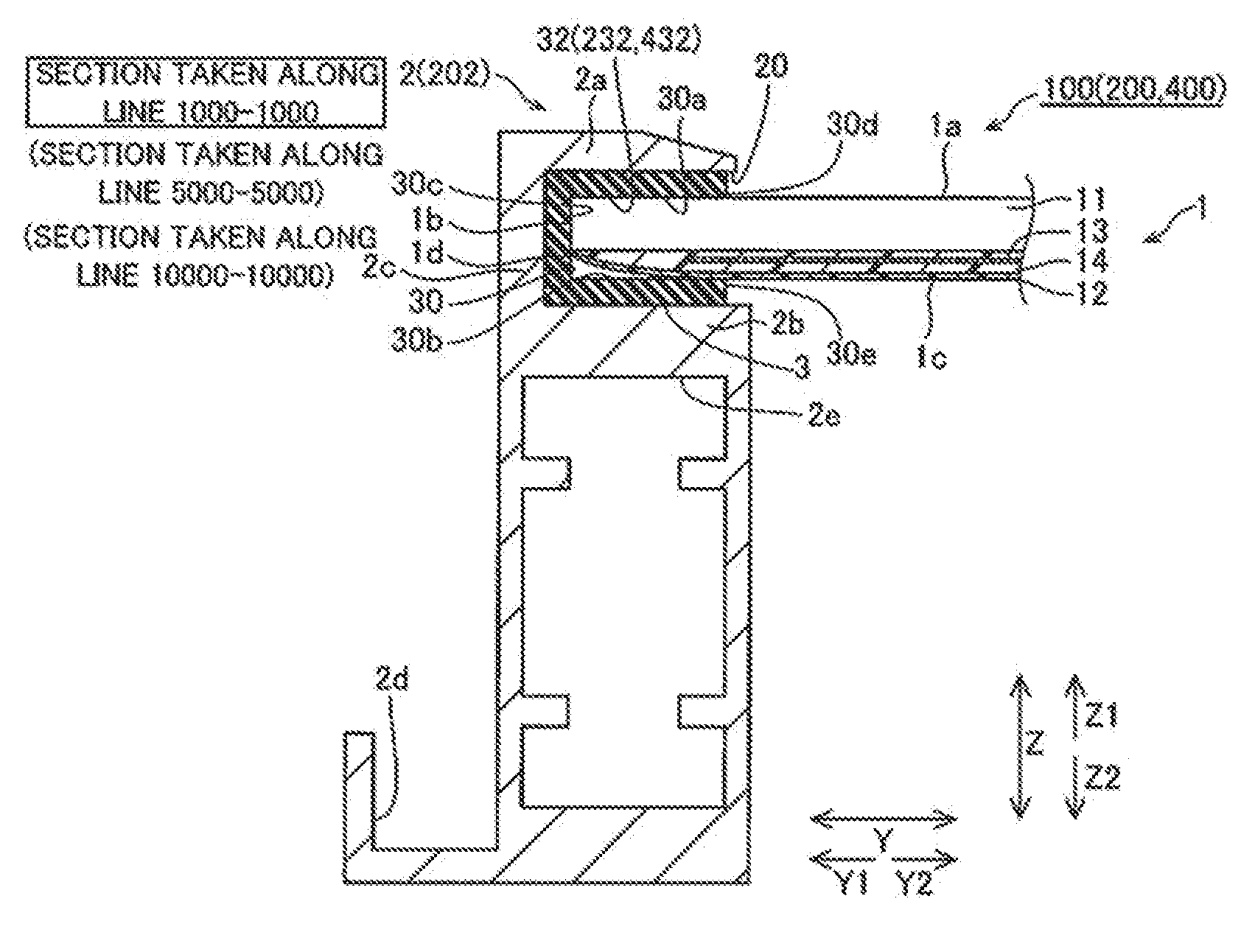
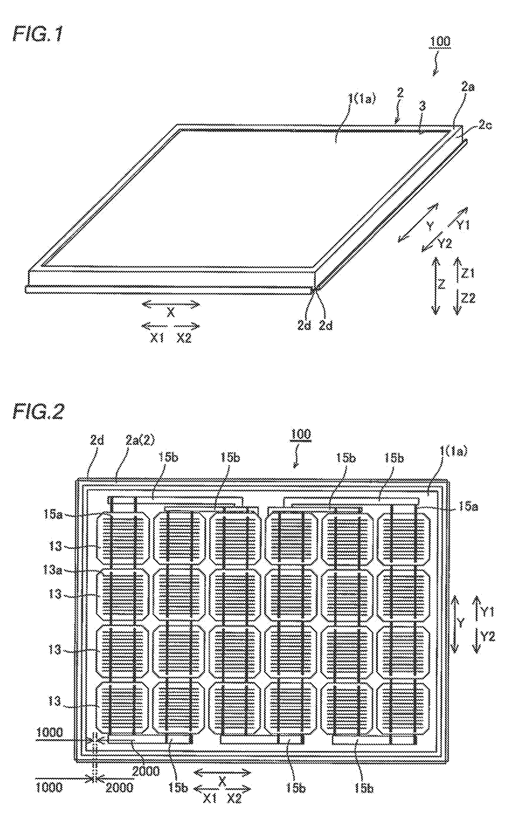
[0062]As shown in FIGS. 1 and 2, a solar cell module 100 according to a first embodiment is constituted by a solar cell panel 1, a frame body 2 made of metal such as aluminum to support the solar cell panel 1, and a gasket 3 (see FIG. 1) made of rubber or the like arranged between the solar cell panel 1 and the frame body 2. In plan view, the solar cell panel 1 has a substantially rectangular shape.

[0063]As shown in FIG. 3, the solar cell panel 1 is constituted by a water-resistant upper surface-side cover 11 made of glass, a weather-resistant lower surface-side cover 12 made of a resin film of polyethylene terephthalate (PET) or the like, a plurality of solar cells 13 arranged between the upper surface-side cover 11 and the lower surface-side cover 12, and a filler 14 provided between the upper surface-side cover 11 (lower surface-side cover 12) and the plurality of solar cells 13. The upper surface-side cover 11 is an example of the “upper surface cover portion” in the present inv...

second embodiment

Modification of Second Embodiment

[0089]Next, a solar cell module 300 according to a modification of the second embodiment of the present invention is described with reference to FIGS. 17 to 20. In this modification of the second embodiment, a gasket 303 is constituted by an upper gasket 340 and a lower gasket 350, dissimilarly to the aforementioned second embodiment in which the gasket 203 is integrally formed.

[0090]As shown in FIGS. 17 and 18, the gasket 303 of the solar cell module 300 according to the modification of the second embodiment is constituted by the upper gasket 340 and the lower gasket 350. This upper gasket 340 is formed with an upper surface portion 341, protrusion portions 342 formed at constant intervals to protrude downward (along arrow Z2) from the upper surface portion 341, and contact portions 343 formed on a side opposite to a side from which a solar cell panel 1 is inserted (see FIGS. 19 and 20), extending downward from the protrusion portions 342. These pro...

third embodiment

Modification of Third Embodiment

[0102]Next, a solar cell module 500 according to a modification of the third embodiment of the present invention is described with reference to FIG. 25. In this modification of the third embodiment, discharge holes 502g are provided in a lower portion 2b of a frame body 502, dissimilarly to the aforementioned third embodiment in which the discharge holes 202f are formed in the side surface portions 2c of the frame body 202.

[0103]As shown in FIG. 25, the discharge holes 502g are formed in the lower portion 2b of the frame body 502 of the solar cell module 500 according to the modification of the third embodiment. The discharge holes 502g are formed to pass through the lower portion 2b of the frame body 502 in a direction Z. Thus, water reaching the discharge holes 502g through grooves 431 and notches 434 of a gasket 403 passes through the discharge holes 502g and hollow portions 2e, and thereafter is discharged to external portions (outer peripheral gr...


PUM


Abstract

There is provided a solar cell module capable of discharging water retained on the upper surface of a solar cell panel therefrom while maintaining the mechanical strength of a frame body. This solar cell module includes a gasket including a groove to discharge the water retained on the upper surface of the solar cell panel, arranged between the solar cell panel and the frame body.

Description

CROSS-REFERENCE TO RELATED APPLICATIONS[0001]The priority application number JP2010-016445, Solar Cell Module, Jan. 28, 2010, Yusaku Tago and Yasuo Kadonaga, upon which this patent application is based is hereby incorporated by reference. This application is a continuation of PCT / JP2011 / 050748, Solar Cell Module, Jan. 18, 2011, Yusaku Tago and Yasuo Kadonaga.BACKGROUND OF THE INVENTION[0002]1. Field of the Invention[0003]The present invention relates to a solar cell module, and more particularly, it relates to a solar cell module including a gasket.[0004]2. Description of the Background Art[0005]A solar cell module including a gasket is known in general, as disclosed in Japanese Patent Laying-Open No. 2000-243998, for example.[0006]The aforementioned Japanese Patent Laying-Open No. 2000-243998 discloses a solar cell module including a solar cell panel, an outer frame fixing the solar cell panel by holding end portions of the solar cell panel by an upper portion, a lower portion, and...

Claims


Application Information

Patent Timeline
Patent Type & Authority Applications(United States)
IPC IPC(8): H01L31/0203
CPCH02S30/10Y02E10/50
Inventor TAGO, YUSAKUKADONAGA, YASUO
Owner SANYO ELECTRIC CO LTD
Learn More