Printing head substrate, ink jet printing head and ink jet printing apparatus with substrate temperature detecting element

a technology of temperature detection and printing head, which is applied in the direction of printing, other printing apparatus, etc., can solve the problems of increasing chip size, substrate size, and mechanical strength of the substrate itself, and achieve the effect of accurate detection of temperature state and improving also mechanical strength of the printing head substra

Inactive Publication Date: 2011-12-06
CANON KK
View PDF6 Cites 16 Cited by
  • Summary
  • Abstract
  • Description
  • Claims
  • Application Information

AI Technical Summary

Benefits of technology

[0013]The present invention is made in view of the forgoing problems and an object of the present invention is to provide a printing head substrate, an ink jet printing head and an ink jet printing apparatus, which accurately detect a temperature state in the central part of a heater array on the substrate and restrict an area of the substrate to a minimum. Another object of the present invention is to provide a printing head substrate, an ink jet printing head and an ink jet printing apparatus, which improve also a mechanical strength of the printing head substrate.
[0015]According to the above construction, providing the beam at the ink supply opening causes the temperature monitor even in the central part of the substrate to be carried out accurately. Since the substrate temperature detecting element is formed on the beam integral with the ink supply opening, a further space for the substrate temperature detecting element is not required and therefore, the downsizing of the printing substrate is possible. In addition, due to the formation of the beam, even the elongated substrate of a large aspect ratio can maintain a mechanical strength of the substrate.

Problems solved by technology

This problem is the more remarkable as the printing head substrate becomes the longer.
That is, in a case of locating the temperature detecting element at the central part of the heater array, it leads to an increase in chip size, that is, substrate size.
However, when the logic circuit is too close to the heater, it possibly causes instability in an operation thereof due to heat and therefore, it is required to locate the temperature sensor near the heater and locate the logic circuit at a position where it is not so much influenced by heat of the heater.
Such a substrate of a large aspect ratio also possibly creates the problem with a mechanical strength of the substrate itself.

Method used


Image

  • Printing head substrate, ink jet printing head and ink jet printing apparatus with substrate temperature detecting element
  • Printing head substrate, ink jet printing head and ink jet printing apparatus with substrate temperature detecting element
  • Printing head substrate, ink jet printing head and ink jet printing apparatus with substrate temperature detecting element

Examples


first embodiment

1. Printing Apparatus

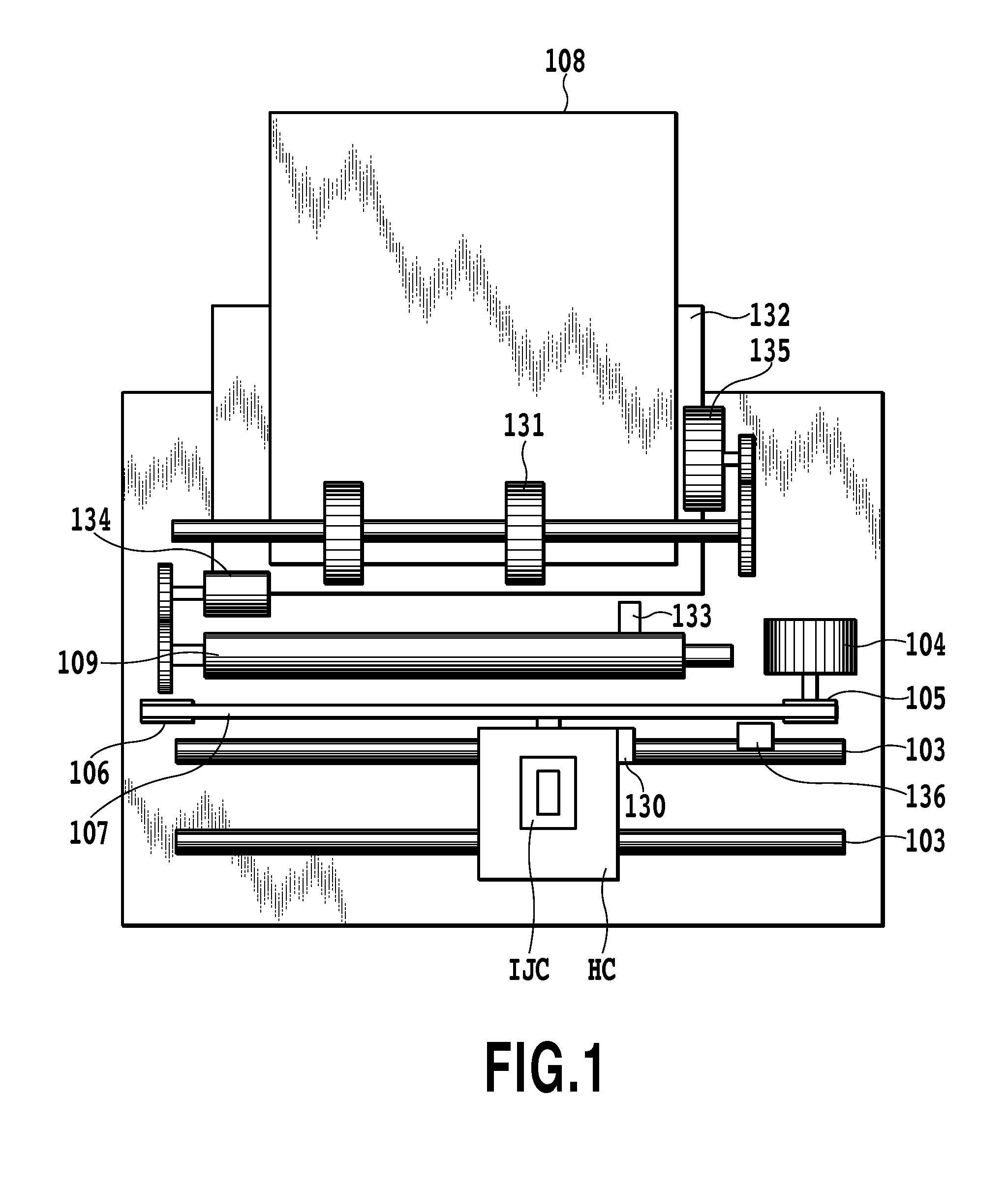
[0040]FIG. 1 is a schematic diagram showing a printing apparatus of the present embodiment.

[0041]A printing head cartridge IJC is configured by combining a printing head IJH provided with a printing head substrate to be described later with a container accommodating ink. The printing head cartridge IJC is positioned at a carriage HC and is mounted thereon to be replaceable. The carriage HC is provided with an electrical connection portion for transmitting a drive signal through an external signal input terminal on the printing head cartridge IJC to each ejection opening.

[0042]The carriage HC is guided and supported by guide shafts 103 disposed in an apparatus to extend in a main scan direction in such a manner as to reciprocate along the guide shafts 103. The carriage HC is driven through a drive mechanism such as a motor pulley 105, a driven pulley 106 and a timing belt 107 by a main scan motor 104, and also a position and a movement of the carriage HC are cont...

second embodiment

[0063]In the first embodiment, the beam provided in the printing head substrate is the beam A provided perpendicular to the arrangement direction of the heater array 6 at the center of the ink supply opening 3 and the diode sensor 7-3 is arranged on the beam A, but the present invention is not limited to such a printing head substrate. That is, the configuration of the beam is not necessarily perpendicular to the arrangement direction of the heater array, but the beam may be formed in any configuration as long as the beam integral with the printing head substrate is provided at the ink supply opening 3 and the temperature detecting element is arranged on the beam.

[0064]FIG. 9 is a schematic diagram showing the construction of a printing head substrate in the present embodiment. This construction is formed by changing the structure of the beam A provided in the supply opening 3 in the first embodiment into a structure of a beam B. The respective members other than the beam B in the p...

third embodiment

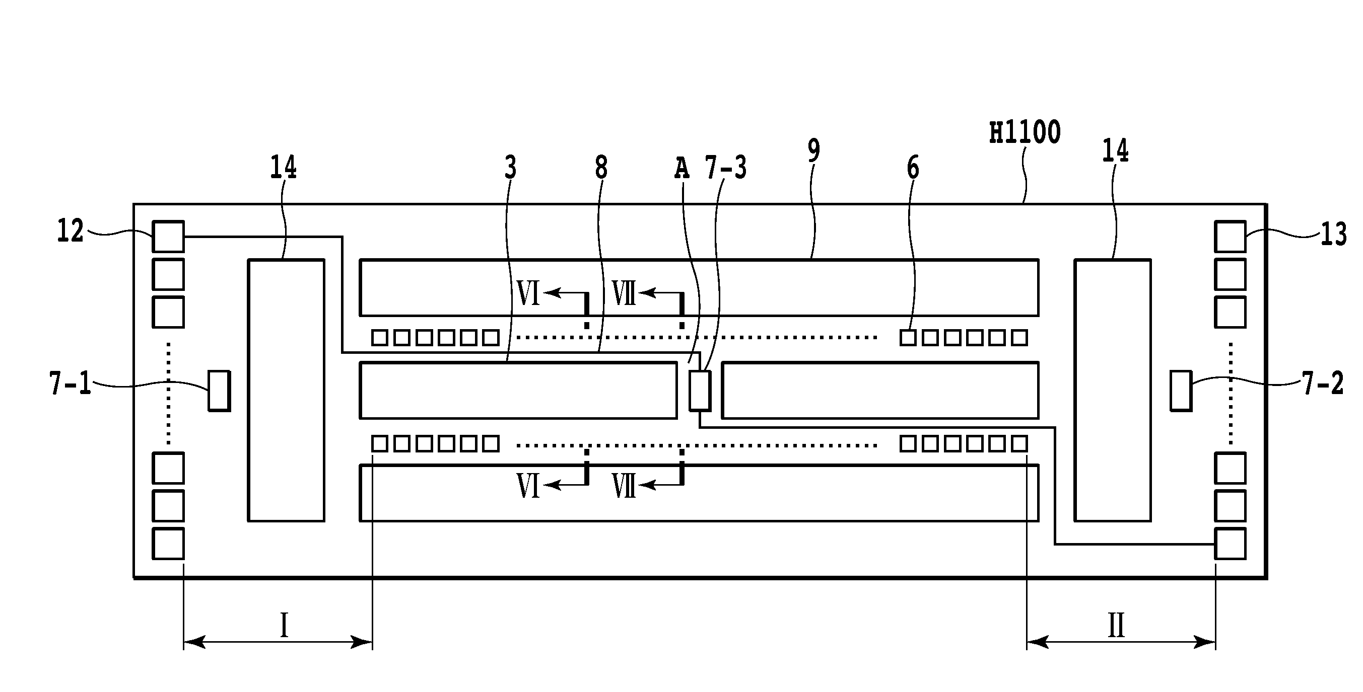
[0084]The printing head substrate in the aforementioned embodiment is provided with the beam located at the ink supply opening to be integral with the printing head substrate and the temperature detecting element (diode sensor) is arranged on the beam. The present invention may be a printing head substrate provided with a logic circuit such as a shift resister and a driver transistor in such a manner as to individually read out the substrate temperature detecting elements.

[0085]FIG. 17 is a schematic diagram showing a printing head substrate in the present embodiment. The heaters 6 (heating elements) are arranged in one line at one side of the ink supply opening 3 along the ink supply opening 3. Logic circuits 14 such as shift resistors for driving the heaters 6 are arranged at both sides of each heater array 6, and a driver transistor (driver 9) for heater drive is arranged in parallel with the heater array 6. The external connection terminals 12 and 13 such as power source termina...


PUM


Abstract

There are provided a printing head substrate, an ink jet printing head and an ink jet printing apparatus, which accurately detect a temperature state in the central part of a heater array on the substrate and restrict an area of the substrate to a minimum. A printing head substrate has a plurality of heating elements, a plurality of ink supply openings, a logic circuit for driving the heating elements; a substrate temperature detecting element for detecting a temperature of the printing head substrate, and input and output pads for carrying out reception and supply of a signal between a printing apparatus, and the logic circuit and the substrate temperature detecting element, wherein a beam integral with the substrate is provided between the plurality of ink supply openings, and the substrate temperature detecting element is arranged on the beam.

Description

BACKGROUND OF THE INVENTION[0001]1. Field of the Invention[0002]The present invention relates to a printing head substrate, an ink jet printing head and an ink jet printing apparatus, and particularly, to a printing head substrate, an ink jet printing head and an ink jet printing apparatus, which are provided with a substrate temperature detecting element.[0003]2. Description of the Related Art[0004]An ink jet printing head mounted in an ink jet printing apparatus ejects ink droplets from ejection openings in various ways to attach the ink droplets onto a print medium such as a print paper, thus carrying out the printing. Among others, the ink jet printing head using heat as energy for ejecting ink can relatively easily realize a multi-nozzle system in high concentration, carrying out the printing with high resolution, of high image quality and at high speeds. There is known a so-called side shooter type of ink jet printing head as one of systems for ejecting ink using this kind of ...

Claims


Application Information

Patent Timeline
Patent Type & Authority Patents(United States)
IPC IPC(8): B41J2/05
CPCB41J2/04563B41J2/0458B41J2/04588B41J2/1408B41J2/1752B41J2/17553
Inventor OOHASHI, RYOJIIMANAKA, YOSHIYUKIOMATA, KOICHITAMURA, HIDEOYAMAGUCHI, TAKAAKIKUBO, KOUSUKETAMARU, YUUJITAKIMOTO, MASAFUMI
Owner CANON KK
Why Eureka
Try Eureka