Welding torch

a welding torch and tip technology, applied in the field of welding torch, can solve the problems of increasing the frequency of tip replacement, increasing and needing to replace the tip, so as to improve the welding and tip replacement efficiency. , the effect of reducing the size of the entire welding torch

Inactive Publication Date: 2012-11-15
KOBE STEEL LTD
View PDF2 Cites 30 Cited by
  • Summary
  • Abstract
  • Description
  • Claims
  • Application Information

AI Technical Summary

Benefits of technology

[0012]The present invention has been made in view of these circumstances, and an object thereof is to provide a compact welding torch with reduced tip wear, reduced tip-replacement frequency, and improved tip-replacement efficiency.

Problems solved by technology

Because the tip is gradually worn away due to friction with the welding wire during the welding operation, the tip needs to be replaced depending on the amount of wear.
Once the tip is worn away, a gap is produced between the tip and the welding wire passing therethrough, resulting in poor contact between the tip and the welding wire.
However, when arc welding is performed with high electric current, the tip is heated by the resistance between the tip and the welding wire and is worn away quickly, increasing the tip-replacement frequency.
Furthermore, increased tip-replacement frequency lowers the operation efficiency because the welding operation is often interrupted.
Furthermore, with such a large welding electrode, the welding area during welding is limited due to the presence of the contact control cylinder and the urging roller.
Although the GMA welding method disclosed in Japanese Unexamined Patent Application Publication No. 2010-194566 (Claims and FIGS. 1 and 2) suggests division of a current supply point, the method is not practical because no specific structure is disclosed therein, and support structures for the tips or the ease of replacement of the tips are not considered.
Such a configuration requires the whole unit to be disassembled when an upper current-supply tip 2 or the lower current-supply tip 3 is replaced due to inevitable wearing or adhesion to the wire, and is time and effort consuming.
Accordingly, this method has little practical use.
In addition, a method illustrated in FIG. 2 of Japanese Unexamined Patent Application Publication No. 2010-194566 does not disclose the details of how an electric current-supply tip 92 is supported at three positions, how it is supplied with electric current, or how it is replaced.

Method used


Image

  • Welding torch
  • Welding torch
  • Welding torch

Examples


first modification

[0072]Although the embodiment of the present invention has been described above, the present invention is not limited to the above-described embodiment, and it may be appropriately modified within a scope not departing from the spirit of the present invention. Note that the configurations already explained will be denoted by the same reference numerals, and the description for such configurations will be omitted. FIG. 7 is a block diagram showing a first modification of the welding torch according to the embodiment of the present invention.

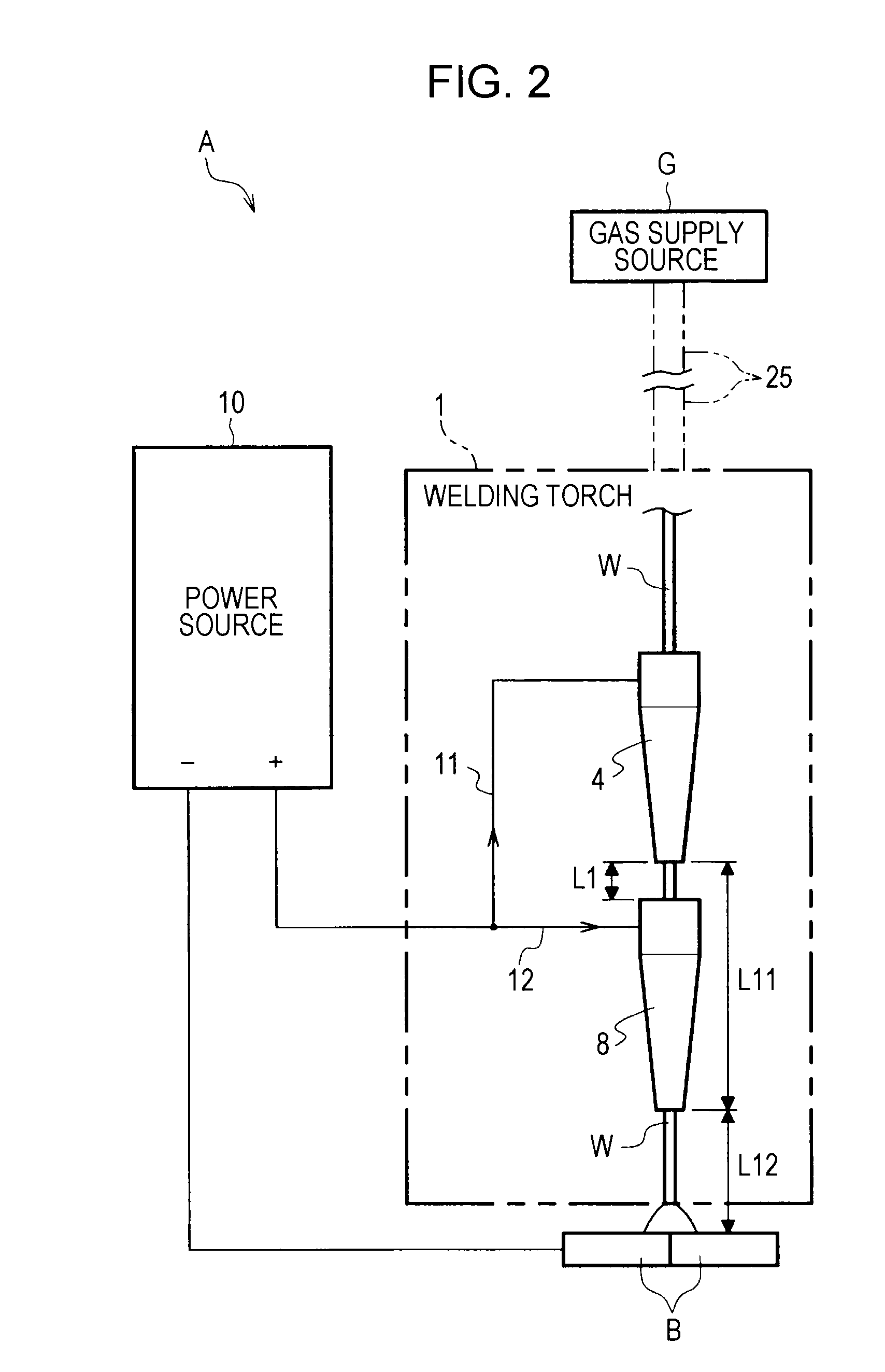
[0073]In the embodiment described above, a configuration in which one power source 10 is used has been described, as shown in FIG. 2. However, the present invention is not limited to such a configuration. For example, as shown in FIG. 7, a power source 10A may include a plurality of power sources, namely, a first power source 10A1 and a second power source 10A2. The first tip 4 and the second tip 8 may be supplied with current from different power...

second modification

[0074]Furthermore, the power source 10A including the first power source 10A1 and the second power source 10A2, shown in FIG. 7, may be configured such that the first power source 10A1 is a pulse power source that supplies pulsed electric current to the welding wire W, and the pulsed electric current outputted from the first power source 10A1 may be synchronized with the timing of pulsed electric current outputted from the second power source 10A2.

third modification

[0075]FIG. 8 is an electrical block diagram showing a third modification of the welding torch according to the embodiment of the present invention. As shown in FIG. 8, the first tip 4 and the second tip 8 may be connected to the power source 10 via variable resistors 14 and 14. With this configuration, electric current supplied from the power source 10 to the first tip 4 and the second tip 8 can be appropriately adjusted by the variable resistors 14 and 14.


PUM

PropertyMeasurementUnit
currentaaaaaaaaaa
distanceaaaaaaaaaa
diameteraaaaaaaaaa

Abstract

A welding torch includes: a first tip body to which a welding wire, gas, and current having passed through a torch body is supplied; a first tip provided at a distal end of the first tip body to supply electric current having passed through the first tip body to the welding wire; an insulating bushing provided inside the nozzle, on the outer periphery of the first tip body; a second tip body to which electric current from a power source is supplied; and a second tip provided at the distal end of the second tip body to supply the current having passed through the second tip body to the welding wire. The first tip and the second tip are axially arranged at a predetermined distance and supply electric current to the welding wire.

Description

BACKGROUND OF THE INVENTION[0001]1. Field of the Invention[0002]The present invention relates to a welding torch used for gas-shielded arc welding.[0003]2. Description of the Related Art[0004]Japanese Unexamined Patent Application Publication No. 10-328836 (Claims and FIGS. 1 and 2) discloses a welding torch of a gas-shielded arc welding apparatus in which a contact tip (hereinbelow, a “tip”) that supplies electric current to a welding wire extending therethrough is provided at a distal end portion of a tip body (a “contact tip holder” in Japanese Unexamined Patent Application Publication No. 10-328836), which is removably attached to a torch body.[0005]Conventionally, a welding wire is fed to a welding torch, passes through a torch body and a tip body, and is fed out of a tip. Electric current is supplied from a power source to the tip and the welding wire, whereby welding is performed. Because the tip is gradually worn away due to friction with the welding wire during the welding ...

Claims


Application Information

Patent Timeline
Patent Type & Authority Applications(United States)
IPC IPC(8): B23K9/16
CPCB23K9/295B23K9/173B23K9/26B23K9/29
Inventor YUAN, YIMINSUZUKI, REIICHIYAMAZAKI, KEI
Owner KOBE STEEL LTD
Why Eureka
Try Eureka