
Space-adaptive wireless power transfer system and method using evanescent field resonance

a wireless power transfer and space-adaptive technology, applied in the field of space-adaptive magnetically coupled resonance wireless power transfer system and method, can solve the problems of low efficiency, power can only be transmitted within a short range of a few centimeters, using magnetic induction, etc., and achieve the effect of improving power transfer efficiency and greater effective power transmitting distan

Active Publication Date: 2012-11-15
KOREA ELECTROTECH RES INST
View PDF23 Cites 44 Cited by
  • Summary
  • Abstract
  • Description
  • Claims
  • Application Information

AI Technical Summary

Benefits of technology

[0026]According to the space-adaptive magnetic resonance wireless power transfer system and method according to the present invention, limitations present when applying power transfer to practical use using the existing parallel arrangement (i.e., when the center axes of Tx and Rx resonant coils are identical with each other) can be overcome. In the case of the existing parallel arrangement, when the distance between transmission and reception increases, there are frequent occasions in which a new intermediate coil may not be placed in parallel to Tx and Rx resonant coils (i.e., when the center axes of coils are identical with each other) because an obstacle is present between Tx and Rx coils or because the spatial limitation is imposed on Tx and Rx. For this reason, there is a limit to the reception of power using the existing parallel arrangement.
[0027]If the arrangement having a right angle or specific angle of inclination is used as in the present invention, however, the existing disadvantages may be negated because the power transmitting unit is contained in a wall or a place not visible. That is, since the resonant coils can be arranged to suit the surrounding environment, the effective power transmitting distance is greater, and the power transfer efficiency is improved. This is based on the characteristic that the magnetically-coupled resonance method is rarely influenced by an obstacle, such as the surface of a wall or water. A location where there is power transfer can be used as the position of the Rx resonant coil, and therefore the Tx resonant coil can be installed in the desired location. The Rx resonant coil can be placed under a desk or contained in the bottom because the Rx resonant coil is formed of only a coil in a helical or spiral form without additionally connecting an electric wire to the coil.

Problems solved by technology

However, the method using magnetic induction is disadvantageous in that power can be transmitted only within a short range of a few centimeters.
Furthermore, there are many difficulties in applying this method using magnetic induction to wireless power transfer systems because it has very low efficiency when the arrangements of Tx and Rx coils are not identical with each other.
However, this invention has a disadvantage in that it is difficult to precisely adjust the value of the variable capacitor to a value which matches the resonant frequency.
Furthermore, this preceding patent discloses wireless power transfer using only a parallel arrangement between the resonant coils, and therefore it is difficult to put this prior patent to practical use in a variety of ways.
If all the resonant coils are on the same plane, the coupling constant between the resonant coils is reduced, and transmission efficiency is deteriorated.
If only the parallel arrangement is used, however, there is the need for a solution capable of solving difficulties that occur when the parallel arrangement is applied to real life because of spatial limitations.
Furthermore, in order to freely situate a power receiving unit, there is the need for a method that enables power transmission even in a vertical arrangement or various arrangements between the transmitting and receiving coils, but there has been no solution for such a method.

Method used


Image

  • Space-adaptive wireless power transfer system and method using evanescent field resonance
  • Space-adaptive wireless power transfer system and method using evanescent field resonance
  • Space-adaptive wireless power transfer system and method using evanescent field resonance

Examples


Embodiment Construction

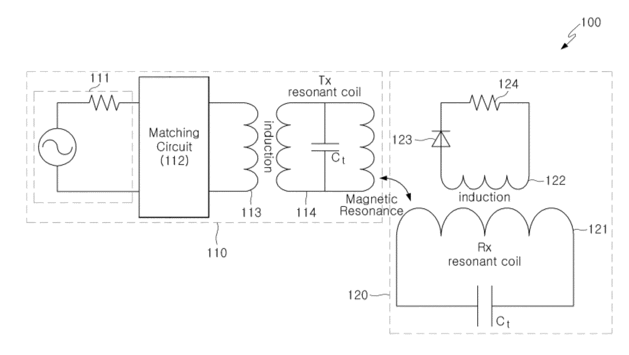
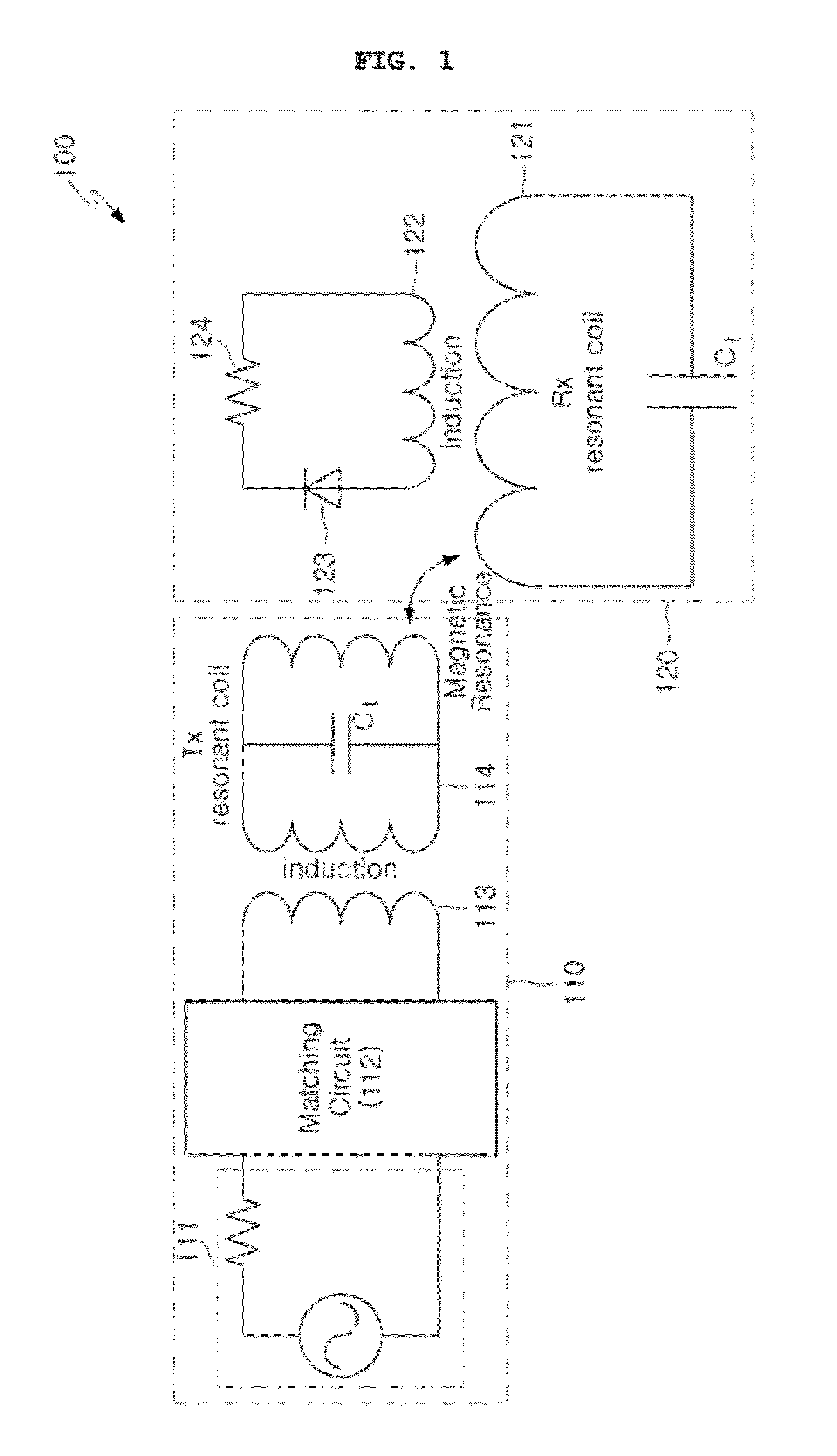
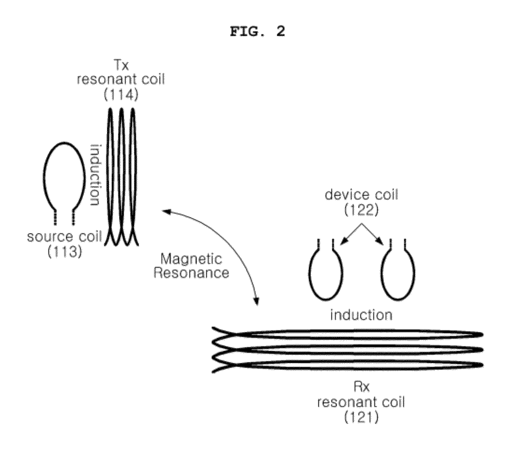
[0060]FIG. 9 shows a variation of the example of FIG. 2 in which the Tx and Rx resonant coils 114 and 121 may be inclined at a specific angle so that they are at a right angle or a specific angle of inclination relative to each other. FIG. 9 shows that the Tx and Rx resonant coils 114 and 121 may be arranged so that the center axes of the Tx and Rx resonant coils 114 and 121 are parallel to each other, but the center axes are not identical with each other because the Tx and Rx resonant coils are not on the same plane.

[0061]FIG. 10 shows a variation of the example of FIG. 3 in which the intermediate resonant coil 131 may be inclined at a specific angle so that it makes a right angle or a specific angle of inclination relative to the Tx resonant coil 114 and the Rx resonant coil 121. FIG. 10 shows that the intermediate resonant coil 131 may be placed so that the intermediate resonant coil 131 is not on the same plane as the Tx resonant coil 114 and the Rx resonant coil 121 and the cen...


PUM


Abstract

A magnetic resonance wireless power transfer method according to an aspect of the present invention includes transmitting power from a source coil to the Tx resonant coil using a magnetic induction method, transmitting the power from the Tx resonant coil to an Rx resonant coil, having a resonant frequency identical with that of the Tx resonant coil, via magnetically-coupled resonance, and transmitting the power from the Rx resonant coil to the device coil of an electronic device using the magnetic induction method. The Tx resonant coil and the Rx resonant coil are arranged at a right angle or a specific angle of inclination relative to each other.

Description

TECHNICAL FIELD[0001]The present invention relates generally to a wireless power transfer system and method using magnetically-coupled resonance of the evanescent field which is generated around a wireless power transmitting coil and, more particularly, to a space-adaptive magnetically-coupled resonance wireless power transfer system and method, in which the resonant coil of a power receiving unit and the resonant coil of a power transmitting unit are configured to have the same resonant frequency so that magnetic field is coupled between the transmitting (Tx) resonant coil and the receiving (Rx) resonant coil, and the Tx and Rx resonant coils are placed on a plane having a right angle or a specific angle so that power transfer is efficient even when the center axis of the power receiving unit has not been aligned with the center axis of the power transmitting unit (i.e., when the center axis of the power receiving unit has to be vertical to the center axis of the power transmitting...

Claims


Application Information

Patent Timeline
IPC IPC(8): H01F38/14
CPCH01F38/14H02J5/005H01F27/006H02J50/12H02J50/50H03H7/38H04B5/24H04B5/79
Inventor PARK, YOUNG JINLEE, SOON WOKANG, JI MYUNGKIM, JIN WOOKKIM, KWAN HO
Owner KOREA ELECTROTECH RES INST
Learn More