Vehicle drive device

Inactive Publication Date: 2012-11-15
AISIN AW CO LTD
View PDF0 Cites 15 Cited by
  • Summary
  • Abstract
  • Description
  • Claims
  • Application Information

AI Technical Summary

Benefits of technology

[0018]According to this configuration, the lubricant can be supplied to the lubricant storing portion by a simple configuration using gravity and surface tension. In particular

Problems solved by technology

However, in this configuration, the amount of lubricant that is supplied to the inside of the rotor shaft is limited to the amount by which the lubr

Method used


Image

  • Vehicle drive device
  • Vehicle drive device
  • Vehicle drive device

Examples


Embodiment Construction

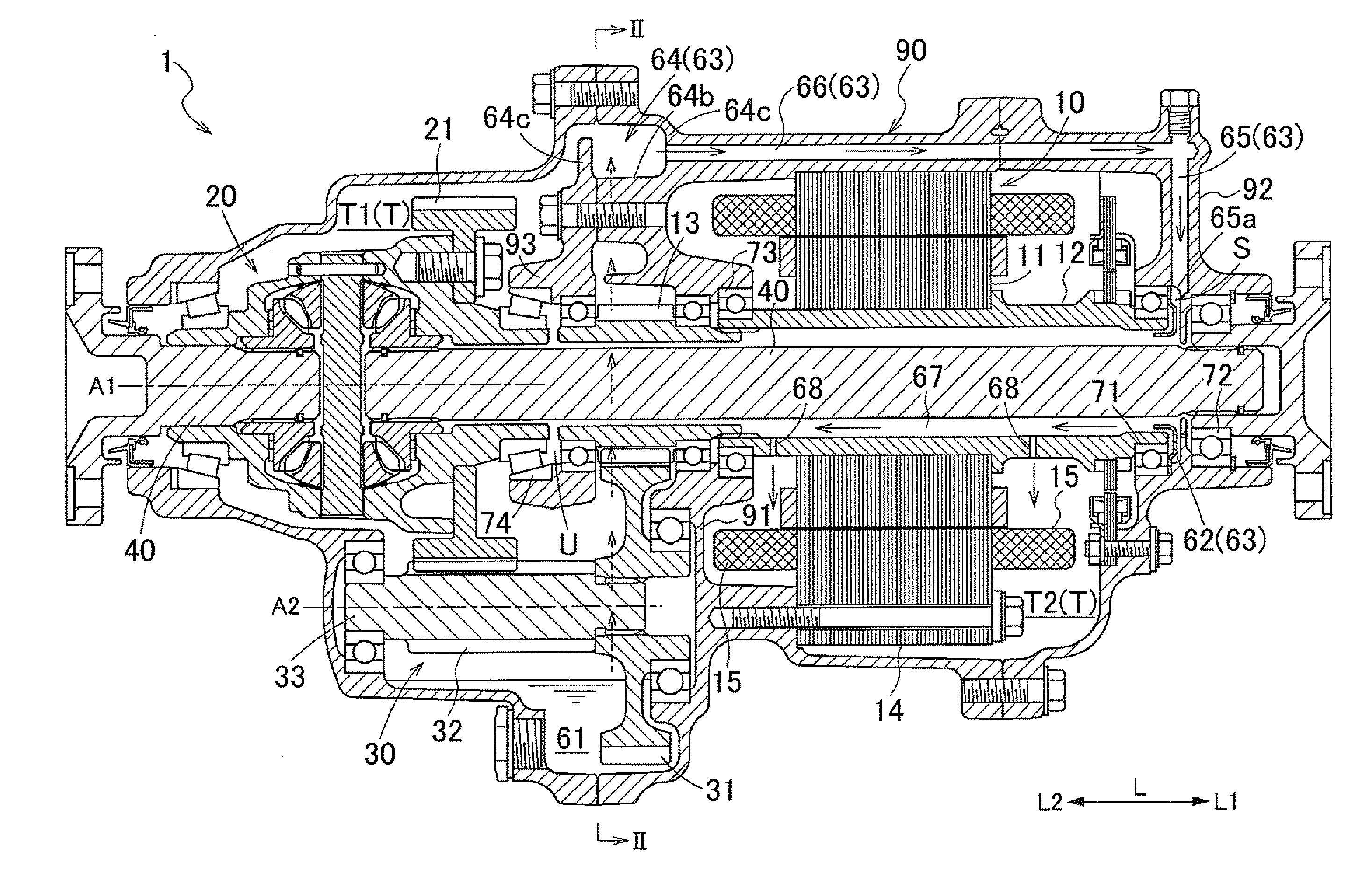
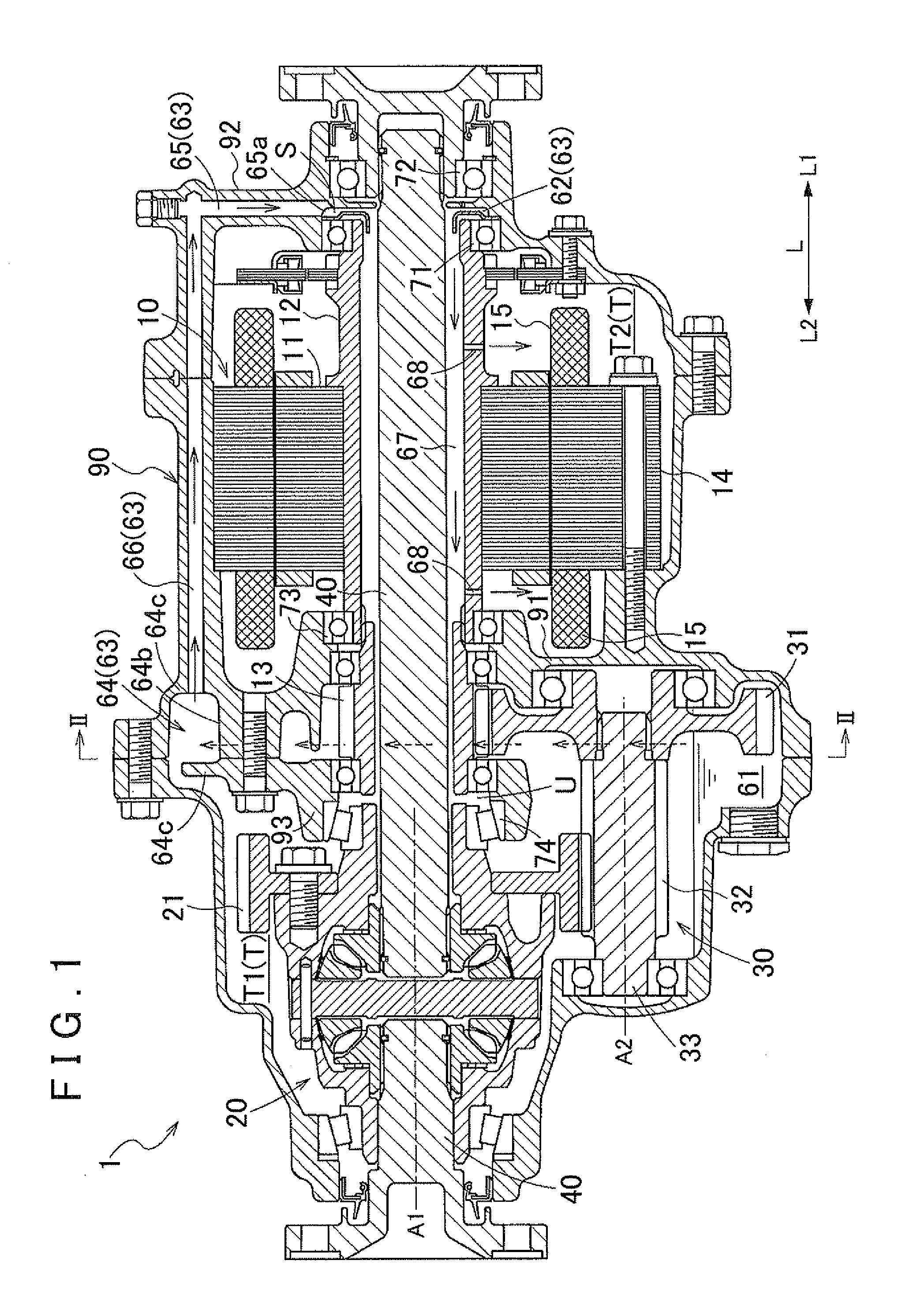
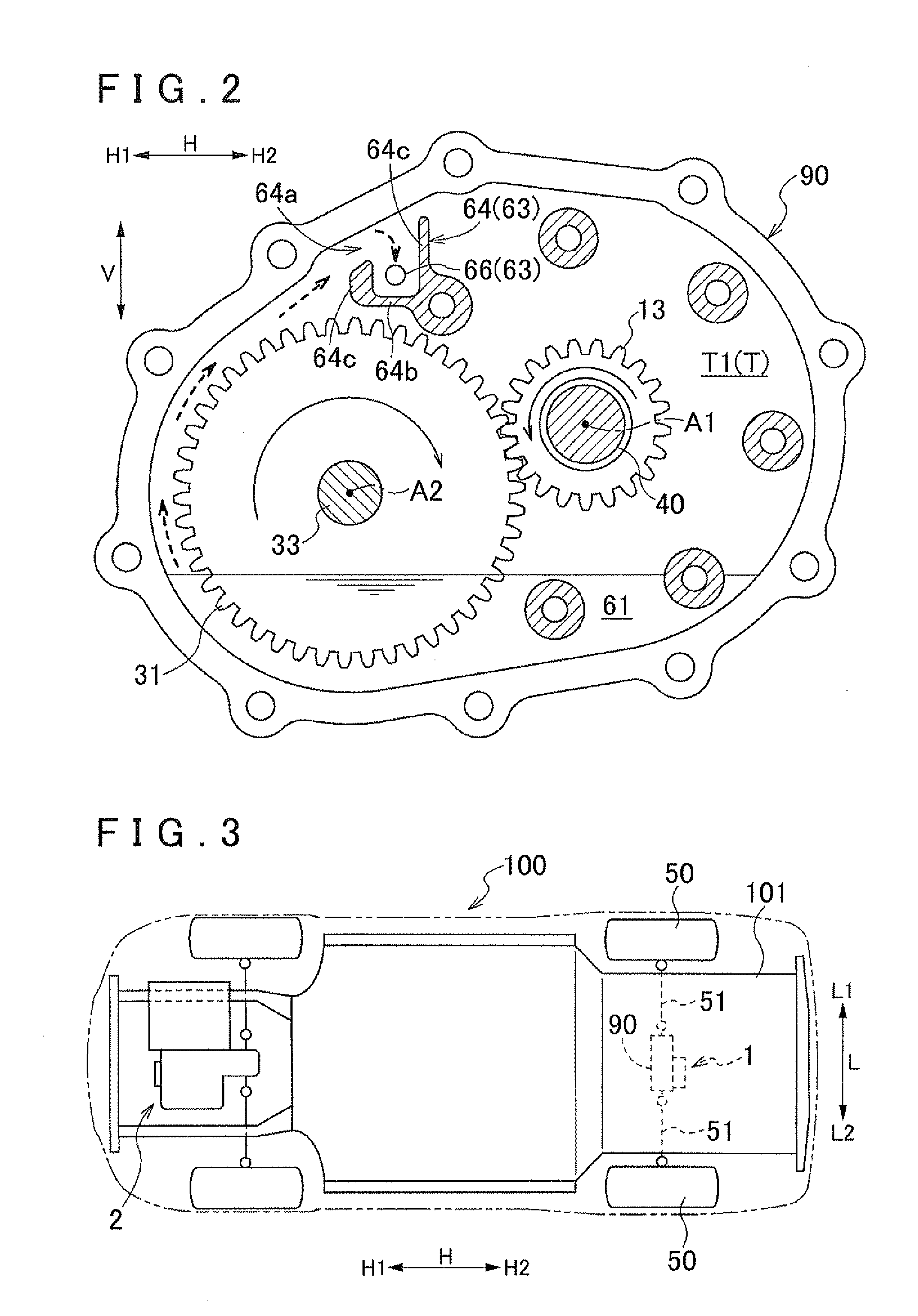
[0025]An embodiment of a vehicle drive device according to the present invention will be described with reference to the accompanying drawings. As shown in FIG. 1, the vehicle drive device (hereinafter simply referred to as the “drive device”) according to the present embodiment includes a rotating electrical machine 10, a differential gear mechanism 20, and a counter gear mechanism 30 in a case 90. A vehicle 100 (see FIG. 3) having the drive device 1 mounted thereon is configured to be able to obtain a driving force for running, by an output torque of the rotating electrical machine 10 which is transmitted to the differential gear mechanism 20 via the counter gear mechanism 30. Specifically, in the present embodiment, as shown in FIG. 3, the drive device 1 is a drive device that drives wheels 50 (rear wheels) on the rear side of the vehicle 100. The configuration of the drive device 1 according to the present embodiment will be described in detail below. In the present embodiment, ...


PUM


Abstract

A vehicle drive device including a rotating electrical machine; a through shaft extending through a rotor shaft of the electrical machine; a power transmission mechanism that transmits power between the rotor shaft and the through shaft; a lubricant supply that supplies lubricant inside of the rotor shaft by rotation of the power transmission mechanism; a first bearing placed radially outward of the rotor shaft to support the rotor shaft; and a second bearing placed radially outward of the through shaft to support the through shaft. The lubricant supply includes a lubricant storing portion located between the first bearing and the second bearing at a position below a rotation central axis of the through shaft. The lubricant storing portion has a portion that communicates with an opening located on an axial first direction side of the rotor shaft, at a position above a lowermost part of the opening.

Description

INCORPORATION BY REFERENCE[0001]The disclosure of Japanese Patent Application No. 2011-106160 filed on May 11, 2011 including the specification, drawings and abstract is incorporated herein by reference in its entirety.BACKGROUND OF THE INVENTION[0002]The present invention relates to vehicle drive devices including a rotating electrical machine, a through shaft placed to extend through a cylindrical rotor shaft of the rotating electrical machine in an axial direction, a power transmission mechanism that transmits power between the rotor shaft and the through shaft, a lubricant supply portion that supplies, to the inside of the rotor shaft, lubricant supplied by rotation of the power transmission mechanism, and a case that accommodates at least the rotating electrical machine and the power transmission mechanism.DESCRIPTION OF THE RELATED ART[0003]For example, there is a technique described in Japanese Patent Application Publication No. JP-A-2005-278319 shown below as related art of ...

Claims


Application Information

Patent Timeline
IPC IPC(8): H02K9/19
CPCB60K2001/001B60K2001/006F16H57/0483F16H57/0476F16H57/0471B60B35/18B60B2900/511B60B2900/561
Inventor SHIMIZU, KATSUTOSHITAKEUCHI, YUYAHONDA, YUYA
Owner AISIN AW CO LTD
Why Eureka
Try Eureka