
High efficacy lighting signal converter and associated methods

Active Publication Date: 2012-11-15
LIGHTING SCI GROUP
View PDF11 Cites 34 Cited by
  • Summary
  • Abstract
  • Description
  • Claims
  • Application Information

AI Technical Summary

Benefits of technology

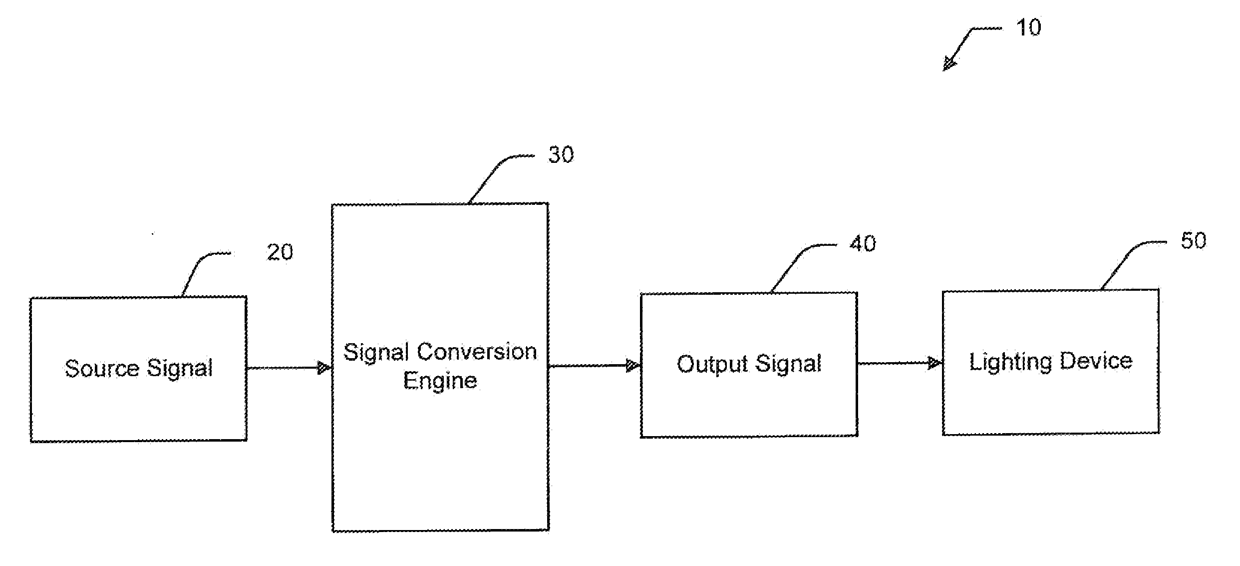
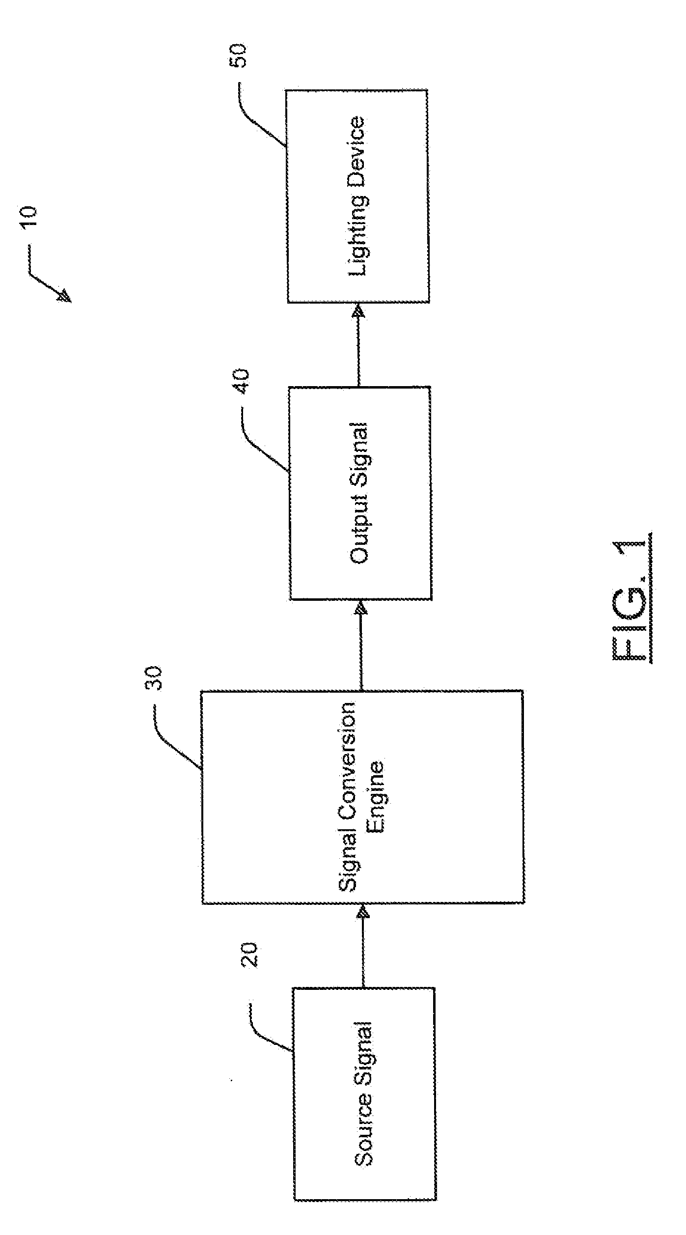
[0010]With the foregoing in mind, it is therefore an object of the present invention to provide a lighting signal converter that may advantageously accept a source signal that defines a colored light in a two spatial plus luminance dimensional color space which includes the full color gamut. More specifically, the present invention may advantageously accept a source input defined by the xyY color space. The present invention may also advantageously produce an output signal that is defined in the three dimensional color space defined by a subset gamut of the full color gamut. The present invention may further output a signal to efficiently drive a minimal number of primary light sources along with a high efficacy light source, advantageously reducing power consumption and heat generation.

Problems solved by technology

In a lighting system that utilizes LEDs to emit light, operating every LED at full luminosity may require using an undesirably large amount of energy and may produce and excessive amount of heat.
However, most lighting source signals do not contemplate the inclusion of a white light source, resulting in signals that cannot drive the white light source of the modified lighting device.
'492 publication requires discarding luminosity values, resulting in potentially inaccurate results.
By adding a new lighting source, the proposed solutions of the prior art may not operate with optimal efficiency characteristics.
As a result, any additional input signal formats, such as the commonly used xyY color space, must first undergo conversion operations which may be computationally intensive and wasteful of energy.
Furthermore, the disclosures in the prior art require the use of light sources defined within the full color gamut to reproduce light in various colors, contributing to inefficient operation of the devices included in the prior art.

Method used


Image

  • High efficacy lighting signal converter and associated methods
  • High efficacy lighting signal converter and associated methods
  • High efficacy lighting signal converter and associated methods

Examples


Embodiment Construction

[0038]The present invention will now be described more fully hereinafter with reference to the accompanying drawings, in which preferred embodiments of the invention are shown. This invention may, however, be embodied in many different forms and should not be construed as limited to the embodiments set forth herein. Rather, these embodiments are provided so that this disclosure will be thorough and complete, and will fully convey the scope of the invention to those skilled in the art. Those of ordinary skill in the art realize that the following descriptions of the embodiments of the present invention are illustrative and are not intended to be limiting in any way. Other embodiments of the present invention will readily suggest themselves to such skilled persons having the benefit of this disclosure. Like numbers refer to like elements throughout.

[0039]In this detailed description of the present invention, a person skilled in the art should note that directional terms, such as “abov...


PUM


Abstract

A signal adapting chromacity system to control that may include a signal conversion engine to receive a source signal designating a color of light defined by a two spatial plus luminance dimensional color space, such as the xxY color space. The signal conversion engine may convert the source signal to a three dimensional color space defined within a subset gamut of a full color gamut, such as an RGW, RBW, or GBW color space. The subset gamut may include a first color light, a second color light and a high efficacy light. The signal conversion engine may perform a conversion operation to convert the source signal to an output signal, using the output signal to drive light emitting diodes (LEDs). The conversion operation may be a matrix, angular or linear conversion operation.

Description

FIELD OF THE INVENTION[0001]The present invention relates to the field of lighting devices and, more specifically, to converting a non-optimized lighting source signal to utilize a high efficacy light emitting semiconductor.BACKGROUND OF THE INVENTION[0002]Some lighting devices are generally capable of emitting light within virtually any color range. This diversity of color emitted may be accomplished via a combination of various colored primary light sources emitting light at varying luminosities. Commonly, in devices that combine light to create various colors, the primary light sources include red, blue, and green colored light.[0003]Red, green, and blue are traditionally known as primary additive colors, or primaries. Additional colors may be created though the combination of the primaries. By combining two additive colors in substantially equal quantities, the secondary colors of cyan, magenta, and yellow may be created. Combing all three primary colors may produce white. By va...

Claims


Application Information

Patent Timeline
IPC IPC(8): H05B37/00H05B44/00
CPCG09G3/3413G09G2320/0666H05B33/0857H05B33/0863G09G2340/06H05B45/20
Inventor MAXIK, FREDRIC S.SOLER, ROBERT R.BARTINE, DAVID E.ZHOU, RANBASTIEN, VALERIE A.REGAN, MATTHEWGROVE, ELIZA KATAR
Owner LIGHTING SCI GROUP
Learn More