Indoor positioning system based on GPS signals and pseudolites with outdoor directional antennas

a positioning system and outdoor technology, applied in waveguide horns, measurement devices, instruments, etc., can solve the problems of signal interference, decrease and the inability of conventional gps receivers to detect outdoor gps signals within buildings, etc., to achieve the effect of increasing the coverage of outdoor gps signals

Inactive Publication Date: 2012-11-15
TEKIN IBRAHIM +2
View PDF0 Cites 24 Cited by
  • Summary
  • Abstract
  • Description
  • Claims
  • Application Information

AI Technical Summary

Benefits of technology

[0013]The object of the invention is to provide an indoor positioning system which increases the coverage of the outdoors GPS signals to indoors.

Problems solved by technology

However, due to additional losses (which are approximately 20-30 dBs) a conventional GPS receiver cannot detect the GPS signals within a building, tunnel, mine or under a debris.
Picking up multiple GPS signals at multiple antennas and then reradiating the same GPS signals from different antennas cause signal interference.
This decreases the GPS signal's coverage as well as increases the error in positioning.
If a conventional GPS receiver with unmodified algorithms is used, then the calculated position becomes erroneous.
If the active RF repeaters are placed to a building to enhance the coverage of the GPS signals indoors and a conventional GPS receiver is used to calculate its location, due to non line of sight (NLOS) propagation of the RF waves from the GPS satellite to the GPS receiver, the calculated position can be the incorrect position with large error.
If the positioning algorithms are not modified, the calculated position can not be correct.
However, deployments of these systems are complex and quite expensive.
This technique suffers from the non-direct propagation of the RF signals from the GPS satellite to RF repeater and then RF repeater to RF GPS receiver.

Method used


Image

  • Indoor positioning system based on GPS signals and pseudolites with outdoor directional antennas
  • Indoor positioning system based on GPS signals and pseudolites with outdoor directional antennas
  • Indoor positioning system based on GPS signals and pseudolites with outdoor directional antennas

Examples


Embodiment Construction

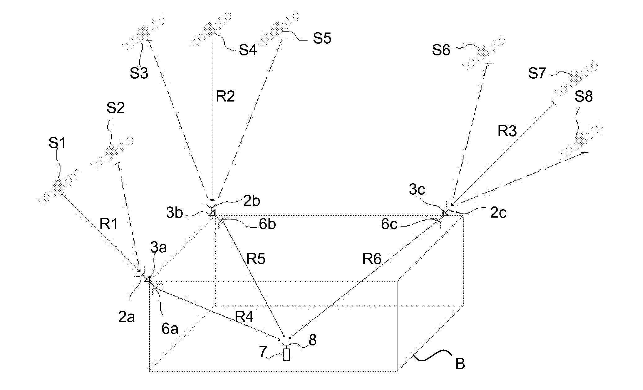
[0045]Referring to FIG. 1, the indoor positioning system (1) comprises at least three directional GPS antennas (2a, 2b and 2c) for picking up specific GPS signals coming from at least three GPS satellites (S1, S4 and S7), at least three RF GPS repeaters (3a, 3b and 3c) for amplifying GPS signals coming from directional GPS antennas (2a, 2b and 2c), at least three GPS antennas (6a, 6b and 6c) for transmitting GPS signals coming from RF GPS repeaters (3a, 3b and 3c) to indoor, at least one GPS receiver (7) for picking up GPS signals coming from GPS antennas (6a, 6b and 6c) by its (7) antenna (8) and position calculation method (100) for calculating the GPS time and finding positioning in two dimensions.

[0046]If there are three RF GPS repeaters (3) then 2D positioning can be done and GPS time can become available.

[0047]If there are four RF GPS repeaters (3), then 3D positioning can be done and GPS time can become available.

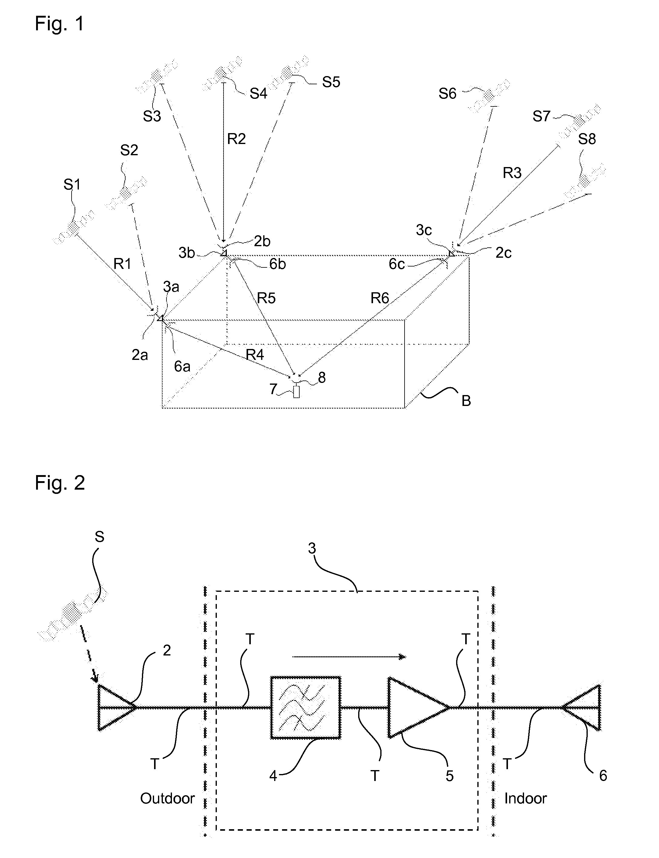
[0048]Referring to FIG. 2, every RF GPS repeaters (3) include a...


PUM


Abstract

This invention comprises at least three directional GPS antennas (2) for picking up specific GPS signals conning from at least three GPS satellites (S), at least three RF GPS repeaters (3) for amplifying GPS signals coming from directional GPS antennas (2), at least three GPS antennas (6) for transmitting GPS signals coming from RF GPS repeaters (3) to indoor, at least one GPS receiver (7) for picking up GPS signals coming from GPS antennas (6) by its (7) antenna (8) novel position calculation method (100) and relates to increase the coverage of the outdoors GPS signals to indoors.

Description

FIELD OF THE INVENTION [0001]This invention relates to an indoor positioning system based on GPS (Global Positioning System) signals for increasing the coverage of the outdoors GPS signals to indoors.PRIOR ART [0002]The GPS is a radio navigation system which provides accurate and reliable positioning, navigation, and timing services freely available to civilian population. The GPS provides location information and accurate time for anybody who has a GPS receiver. The GPS provides location and time information at all time, anywhere on the world.[0003]The GPS system consists of 24 operational GPS satellites rotating around the earth twice a day at an altitude of approximately 20200 km, controlling and monitoring stations on the network side as well as GPS receivers on the user side. GPS satellites transmit RF signals at a frequency of 1575.42 MHz from the space and GPS receivers pick up these RF signals and down convert to an intermediate frequency (IF) for correlation and further bas...

Claims


Application Information

Patent Timeline
Patent Type & Authority Applications(United States)
IPC IPC(8): G01S19/11
CPCG01S19/11H01Q13/02H01Q1/007G01S19/42G01S19/115
Inventor TEKIN, IBRAHIMBOZKURT, AYHANOZSOY, KEREM
Owner TEKIN IBRAHIM
Why Eureka
Try Eureka