
Backlight assembly and method of assembling a backlight assembly

a backlight assembly and assembly technology, applied in the field of backlight assembly and a method of assembling a backlight assembly, can solve the problems of non-uniform luminance, achieve better light efficiency, improve luminance uniformity, and minimize sheet warpage

Active Publication Date: 2012-11-15
SAMSUNG DISPLAY CO LTD
View PDF2 Cites 18 Cited by
  • Summary
  • Abstract
  • Description
  • Claims
  • Application Information

AI Technical Summary

Benefits of technology

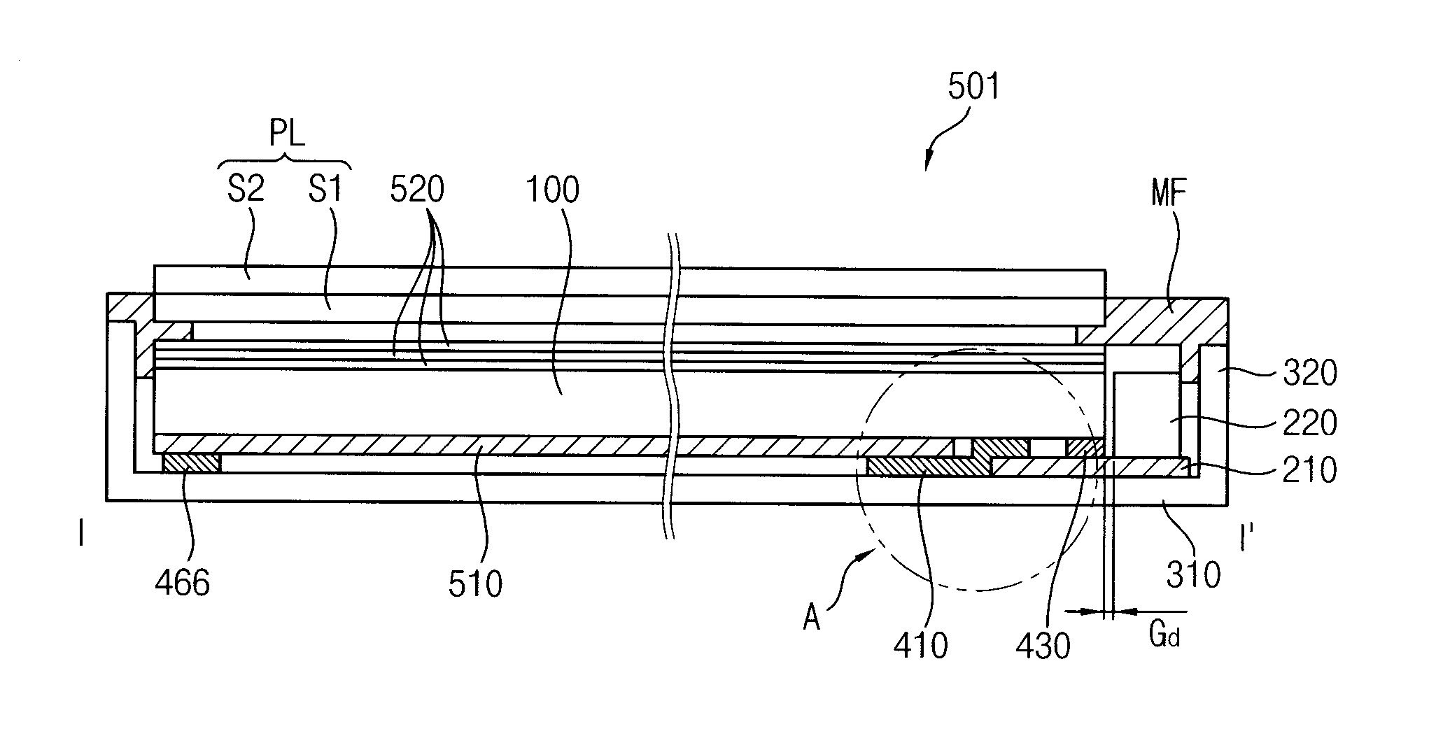
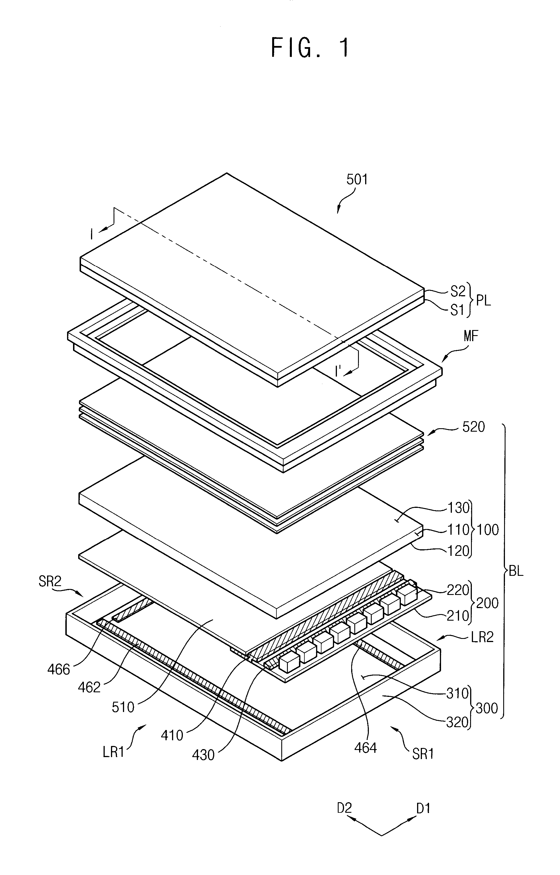
[0008]Exemplary embodiments of the invention provide a backlight assembly capable of stably fixing a light-emitting module, a receiving container and a light guide plate to improve a light efficiency and a uniformity of luminance.
[0009]Exemplary embodiments of the invention also provide a method of assembling a backlight assembly capable of easily assembling a light-emitting module, a receiving container and a light guide plate and improving reliability of the assembling.
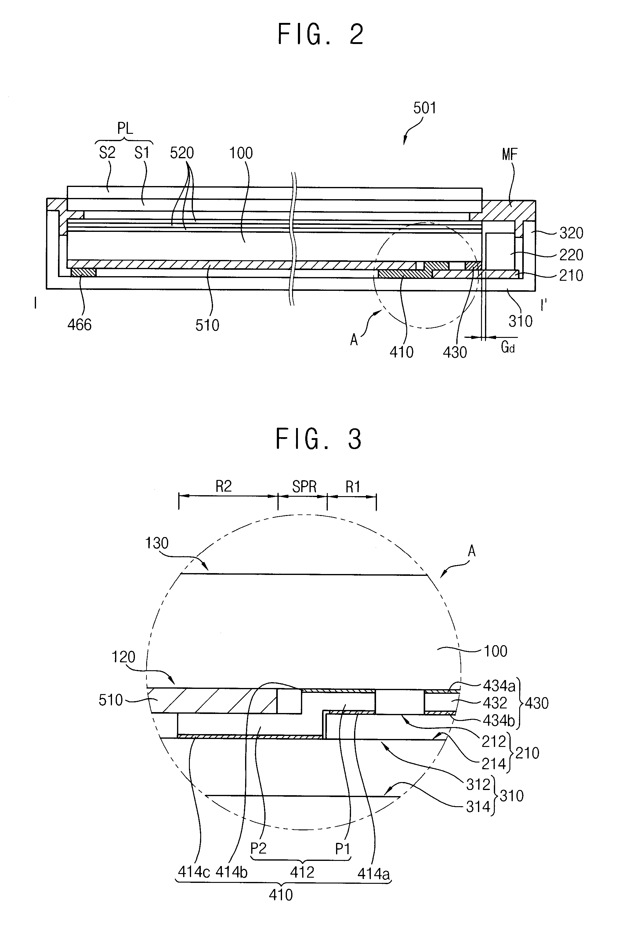
[0022]According to the invention, a light guide plate is stably fixed to a light-emitting module and a receiving container so that a distance between the light guide plate and the light-emitting module may be uniformly maintained. In addition, although the light guide plate is thermally expanded by heat from the light-emitting module, the other elements included in the backlight assembly may shift so that the distance between the light guide plate and the light-emitting module may be not changed. Accordingly, the other elements included in the backlight assembly may be hardly deformed by an expansion of the light guide plate, for example, a sheet warpage may be minimized. Thus, a light is hardly lost by a change of the distance between the light guide plate and the light-emitting module, so that the backlight assembly may have better light efficiency and better luminance uniformity.

Problems solved by technology

In addition, the luminance differs between the first regions directly receiving the light and the second regions indirectly receiving the light, so that the luminance may be non-uniform.

Method used


Image

  • Backlight assembly and method of assembling a backlight assembly
  • Backlight assembly and method of assembling a backlight assembly
  • Backlight assembly and method of assembling a backlight assembly

Examples


Embodiment Construction

[0032]The invention is described more fully hereinafter with reference to the accompanying drawings, in which exemplary embodiments of the invention are shown. This invention may, however, be embodied in many different forms and should not be construed as limited to the exemplary embodiments set forth herein. Rather, these embodiments are provided so that this disclosure will be thorough and complete, and will fully convey the scope of the invention to those skilled in the art. In the drawings, the size and relative sizes of layers and regions may be exaggerated for clarity.

[0033]It will be understood that when an element or layer is referred to as being “on,”“connected to” or “coupled to” another element or layer, the element or layer can be directly on, connected or coupled to another element or layer or intervening elements or layers. In contrast, when an element is referred to as being “directly on,”“directly connected to” or “directly coupled to” another element or layer, there...


PUM

PropertyMeasurementUnit
Adhesion strengthaaaaaaaaaa

Abstract

A backlight assembly includes a first light-emitting module, a light guide plate, a receiving container and a main adhesion member. The first light-emitting module includes a first circuit board including a first mounting surface, and a first light source on the first mounting surface. The light guide plate is on the first mounting surface and guides light from the first light source. The receiving container includes a bottom portion and receives the first light-emitting module and the light guide plate. The main adhesion member is between the first mounting surface and the light guide plate and is attached to the first circuit board and the light guide plate, and is between the light guide plate and the bottom portion and movable with respect to the light guide plate.

Description

[0001]This application claims priority to Korean Patent Application No. 2011-0044896, filed on May 13, 2011, and all the benefits accruing therefrom under 35 U.S.C. §119, the contents of which are herein incorporated by reference in its entirety.BACKGROUND OF THE INVENTION[0002]1. Field of the Invention[0003]Exemplary embodiments of the invention relate to a backlight assembly and a method of assembling a backlight assembly. More particularly, exemplary embodiments of the invention relate to a backlight assembly used for a display apparatus and a method of assembling a backlight assembly.[0004]2. Description of the Related Art[0005]Generally, a display apparatus includes a display panel displaying an image using light and a backlight assembly providing the light to the display panel. The display panel includes a display substrate including a thin-film transistor (“TFT”) for driving a pixel and an opposite substrate facing the display substrate. The display panel includes a liquid cr...

Claims


Application Information

Patent Timeline
IPC IPC(8): G09F13/18B32B37/14F21V13/02
CPCG02F2202/28Y10T156/10G02F1/133608G02F1/1333G02F1/1335G02F1/1339
Inventor LEE, SANG-HWAN
Owner SAMSUNG DISPLAY CO LTD
Learn More