
Device for reworking the running surface of a rail head by machining

a technology for running surfaces and rail heads, which is applied in the direction of milling equipment, railway tracks, track maintenance, etc., can solve the problems of substantial heating of rail heads, limited machining speed, and surface quality degradation, and achieve high processing speed

Inactive Publication Date: 2012-11-15
SCHWEERBAU +1
View PDF8 Cites 21 Cited by
  • Summary
  • Abstract
  • Description
  • Claims
  • Application Information

AI Technical Summary

Benefits of technology

[0005]The invention is therefore based on the object of implementing a device of the type described at the beginning for reworking the running surface of a rail head by machining in such a manner that advantageous running surface machining at a comparatively high processing speed can be ensured, without having to accept excess heat stress of the rail head.
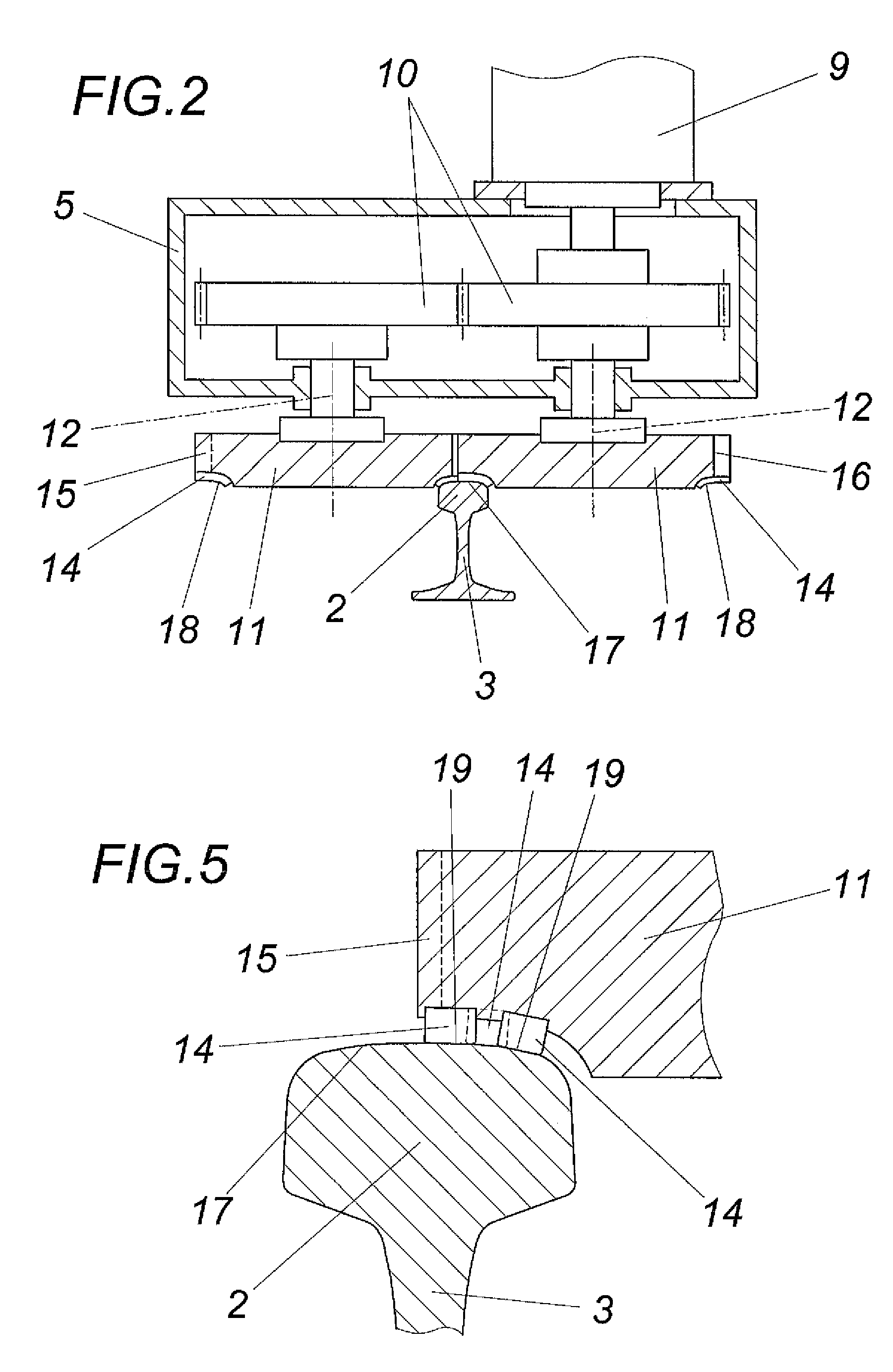
[0007]Through the arrangement of the rotational axes of the face millers, which are mounted in a common framework, in a common plane, the design specifications are provided for attaching these face millers via a transfer case to a common rotational drive, which not only decreases the design effort, but rather also provides the possibility of guiding the two face millers via the common framework along the rail to be machined in such a manner that uniform machining of the two rail head sides by the face millers, which are opposite to one another in relation to the rail head, is made possible. A requirement for this purpose is that the two face millers have at most a limited mutual spacing from one another in the longitudinal direction of the rail head, which is determined by the two intermeshing gear wheels of the transfer case for driving the shafts of the face millers. The rotational axes of the two face millers do not necessarily have to extend parallel to one another. A greater ablation of the running surfaces can be made possible with a correspondingly inclined approach of the face millers.

Problems solved by technology

Because of comparatively high axial loads and high travel speeds, rails are often strained up to the yield point of the rail material and are therefore subject to wear, which has a disadvantageous effect on the profile of the running surface of the rail head, so that for maintenance of the rails, the running surfaces must be reworked.
In such grinding assemblies and also in other grinding assemblies (WO 2003 / 042458 A2), it is disadvantageous that in particular at higher advance speeds, substantial heating of the rail head must be expected, whereby the possible machining speed is restricted.
However, the cutting curve of the individual blades of the milling tool, which is caused by such peripheral milling and is curved in a surface-normal longitudinal plane, results in a wavy surface of the rail head in the rail longitudinal direction, the surface quality worsening with increasing advance speed because of the increasing spacing of the chip removals of successive blades.
In addition to the comparatively large design expenditure, the substantial functional disadvantage results that to machine the side of the rail head opposite to the face miller, a face miller must be used in a comparatively large spacing in the rail longitudinal direction, which results in uneven machining of the two sides of the rail head under certain circumstances.
Similar disadvantages result in the case of another known device (EP 0 148 089 A2), in which the running surface is machined on both sides of the longitudinal center by a milling head, which is designed as a face miller, but must be used having a correspondingly inclined axis, because peripheral millers for the longitudinal sides of the rail head must be arranged before or after this common milling head.

Method used


Image

  • Device for reworking the running surface of a rail head by machining
  • Device for reworking the running surface of a rail head by machining
  • Device for reworking the running surface of a rail head by machining

Examples


Embodiment Construction

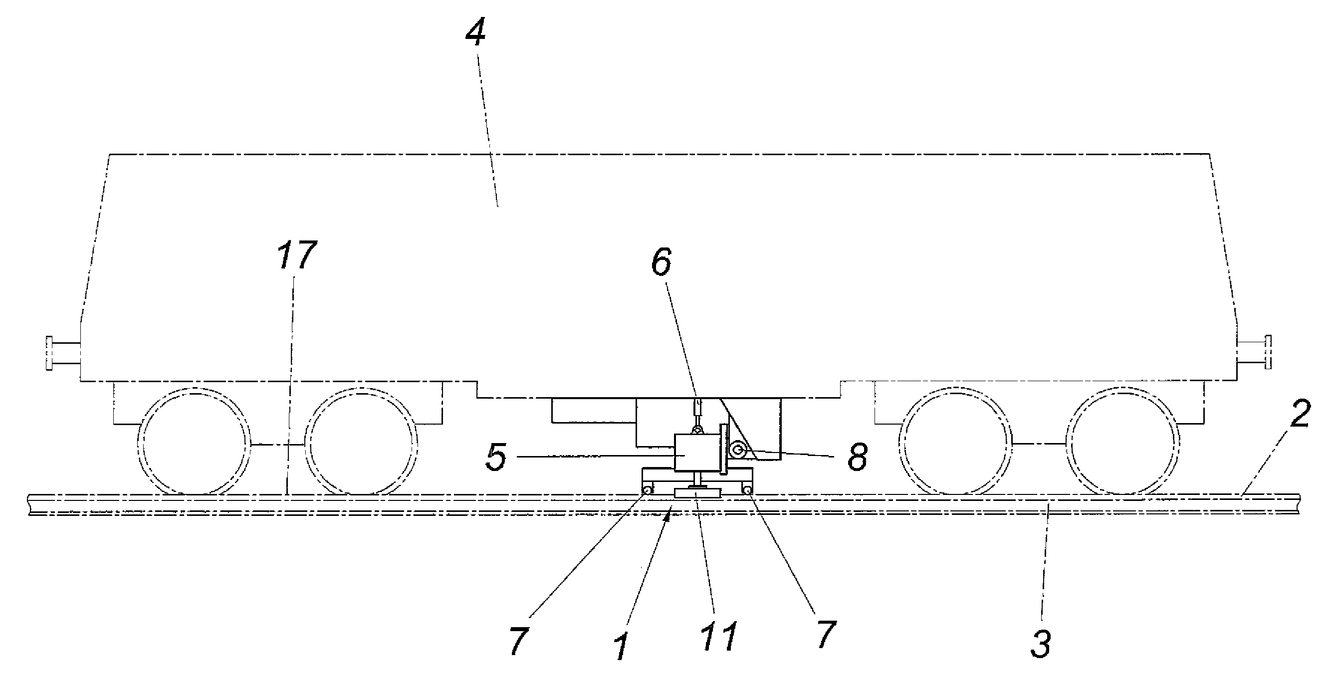
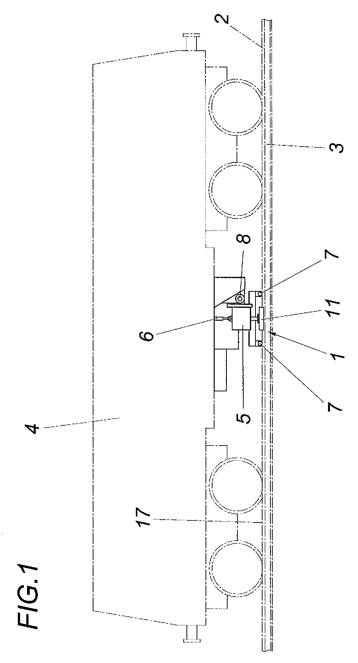
[0019]As can be inferred from FIG. 1, the device 1 according to the invention for reworking the rail head 2 of the rails 3 of a railway track by machining is arranged on a rail vehicle 4, with the aid of which the device 1 is moved along the rail 3. The device 1 has a framework 5 mounted on the rail vehicle 4, which is mounted so it is vertically adjustable with the aid of a lift drive 6 on the rail vehicle 4 and is supported via guide rollers 7 on the rail head 2. These guide rollers 7 not only guide the framework 5 vertically in relation to the rail 3, but rather also laterally.

[0020]According to FIG. 2, the framework 5, which is linked for vertical displacement to the rail vehicle 4 via an axis 8, which is not required, however, receives a transfer case 10, which is connected to a rotational drive 9, for two machining tools drivable synchronously in opposite directions in the form of face millers 11. The rotational axes 12 of these face millers 11 are located in a common plane 13...


PUM


Abstract

A device (1) is described for reworking the running surface (17) of a rail head (2) by machining having a framework (5) guided along the rail head (2), in which two machining tools, which are drivable to rotate in opposite directions and can frontally approach the running surface (17), are mounted on both sides of the rail head (2). In order to be able to provide advantageous machining conditions, it is proposed that the machining tools be designed as face millers (11), whose rotational axes (12) extend in a common plane (13) and whose cutting areas overlap one another transversely to the longitudinal direction of the rail head (2), and the two face millers (11) be connected via a transfer case (10) to a common rotational drive (9).

Description

FIELD OF THE INVENTION[0001]The invention relates to a device for reworking the running surface of a rail head by machining having a framework guided along the rail head, in which two machining tools, which are drivable to rotate in opposite directions and can frontally approach the running surface, are mounted on both sides of the rail head.DESCRIPTION OF THE PRIOR ART[0002]Because of comparatively high axial loads and high travel speeds, rails are often strained up to the yield point of the rail material and are therefore subject to wear, which has a disadvantageous effect on the profile of the running surface of the rail head, so that for maintenance of the rails, the running surfaces must be reworked. For this purpose, grinding assemblies are known (AT 344 772 B), which have at least two cup wheels, which are arranged in succession in the longitudinal direction of the rail head and approach the running surface frontally on opposite sides of the rail head, having a grinding profi...

Claims


Application Information

Patent Timeline
IPC IPC(8): B23C1/00
CPCB23C3/005Y10T409/309352E01B31/13
Inventor RUNGGER, HELMUT
Owner SCHWEERBAU
Learn More