Scintillator panel and method of manufacturing the scintillator panel

a technology of scintillator and scintillator panel, which is applied in the field of scintillator panel, can solve the problems of unavoidable use of film, undesired double cost, and difficult to achieve uniform flatness

Inactive Publication Date: 2012-11-15
ABYZ R
View PDF0 Cites 52 Cited by
  • Summary
  • Abstract
  • Description
  • Claims
  • Application Information

AI Technical Summary

Benefits of technology

[0016]Accordingly, the present invention has been made keeping in mind the above problems occurring in the related art, and an object of the present invention is to provide a scintillator panel which may prevent moisture from penetrating and may have uniform flatness, and a radiation image sensor including the scintillator panel.

Problems solved by technology

Conventional X-ray radiography, which has been carried out using films and screens, is problematic because it requires manpower and space to store the films.
However, this also unavoidably uses up film, undesirably doubling costs.
Furthermore, moisture may penetrate into the interface between the dam 300 and the protective layer 400, undesirably causing problems in which the scintillator layer 200 may undesirably dissolve in moisture that is absorbed.
Furthermore, moisture may directly penetrate into the dam 300 or may penetrate into the interface between the substrate 100 and the dam 300, undesirably causing problems in which the scintillator layer 200 may undesirably dissolve in moisture that is absorbed.
Meanwhile as illustrated in FIG. 1, flatness of the entire scintillator panel is not uniform because of the inclined peripheral surface of the scintillator layer 200, undesirably causing defects in subsequent processes.

Method used


Image

  • Scintillator panel and method of manufacturing the scintillator panel
  • Scintillator panel and method of manufacturing the scintillator panel
  • Scintillator panel and method of manufacturing the scintillator panel

Examples


first embodiment

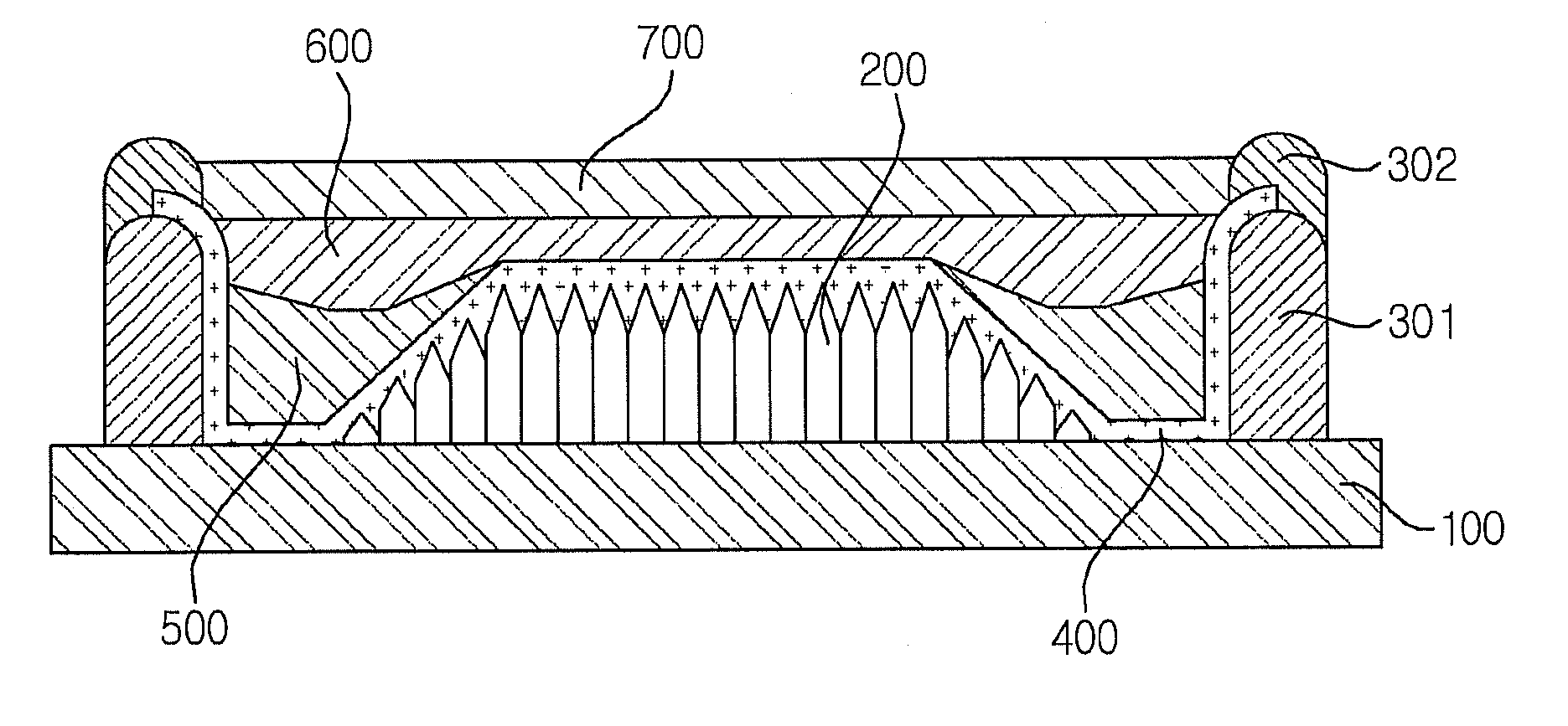
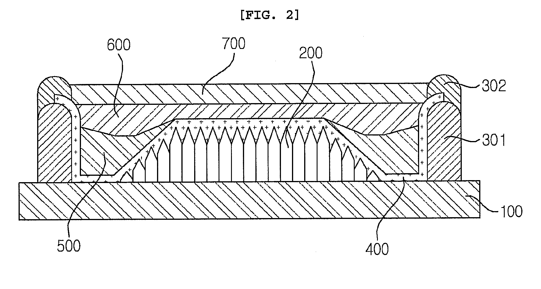
[0056]FIG. 2 illustrates a cross-section of the scintillator panel according to the first embodiment of the present invention. As illustrated in FIG. 2, the scintillator panel according to the first embodiment of the present invention comprises a substrate 100; a scintillator layer 200 formed on the substrate and comprising a plurality of columnar crystals so that radiation is converted into light at a predetermined wavelength; a dam structure 301, 302 formed on the substrate to be spaced apart by a predetermined interval from the peripheral edge of the scintillator layer; a protective layer 400 formed on the surface of the scintillator layer 200, the surface of the substrate 100 defined between the scintillator layer 200 and the dam structure 301, 302, and a portion of the surface of the dam structure 301, 302; a first coating layer 500 formed on the protective layer 400 to be disposed in a space between the peripheral surface of the scintillator layer 200 and the dam structure 301...

second embodiment

[0094]In the second embodiment of the present invention, portions of the description which would overlap with those of the first embodiment are omitted.

[0095]FIG. 3 illustrates a cross-section of the scintillator panel according to the second embodiment of the present invention. As illustrated in FIG. 3, the scintillator panel according to the second embodiment of the present invention is configured such that a scintillator layer 200 is formed on a substrate 100, a first dam 311 is formed on the substrate 100 to be spaced apart by a predetermined interval from the peripheral edge of the scintillator layer 200, and a second dam 312 is positioned around the first dam 311. As such, the sequence of forming the scintillator layer 200, forming the second dam 312 and then forming the first dam 311 inside the second dam 312 is possible. As shown in FIG. 3, the first dam 311 and the second dam 312 have the same height and width, which is merely illustrative, and the height and width may vary...

third embodiment

[0106]In the third embodiment of the present invention, portions of the description which would overlap with those of the first embodiment are omitted.

[0107]FIG. 4 illustrates a cross-section of the scintillator panel according to the third embodiment of the present invention. As illustrated in FIG. 4, the scintillator panel according to the third embodiment of the present invention is configured such that a scintillator layer 200 is formed on a substrate 100, a first dam 321 is formed on the substrate 100 to be spaced apart by a predetermined interval from the peripheral edge of the scintillator layer 200, a second dam 322 is formed around the first dam 321, and a third dam 323 is formed around the second dam 322. As such, the sequence of formation of the first dam 321, the second dam 322 and then the third dam 323 is not necessarily limited to the above, and the sequence of formation of the first dam 321 to the third dam 323 may be altered.

[0108]As shown in FIG. 4, the first dam 3...


PUM

PropertyMeasurementUnit
thicknessaaaaaaaaaa
wavelengthaaaaaaaaaa
heightaaaaaaaaaa

Abstract

Disclosed is a scintillator panel, including a substrate, a scintillator layer formed on the substrate and including a plurality of columnar crystals so that radiation is converted into light at a predetermined wavelength, a dam structure formed on the substrate to be spaced apart by a predetermined interval from a peripheral edge of the scintillator layer, a protective layer formed on a surface of the scintillator layer, a surface of the substrate defined between the scintillator layer and the dam structure and a portion of a surface of the dam structure, a first coating layer formed on the protective layer to be disposed in a space between a peripheral surface of the scintillator layer and the dam structure, and a second coating layer formed on the first coating layer and the protective layer.

Description

BACKGROUND OF THE INVENTION[0001]1. Field of the Invention[0002]The present invention relates to a scintillator panel and a method of manufacturing the same.[0003]2. Description of the Related Art[0004]Conventional X-ray radiography, which has been carried out using films and screens, is problematic because it requires manpower and space to store the films. To solve this problem, attempts have been made to scan such films using a scanner to digitize them. However, this also unavoidably uses up film, undesirably doubling costs. Hence, a digital radiographic imaging apparatus has been introduced in which radiation is converted into an electrical signal using a detector in lieu of a film and such a signal is transmitted to a computer.[0005]Types of digital radiographic imaging apparatuses are a direct conversion type and an indirect conversion type, depending on the type of conversion. The direct conversion type enables the irradiated X-rays to be directly converted into an electrical ...

Claims


Application Information

Patent Timeline
Patent Type & Authority Applications(United States)
IPC IPC(8): B32B3/08
CPCG21K4/00Y10T428/24653G01T1/202G01T1/20H01L31/02
Inventor KUG, YUN BONGHONG, TAEKWONSONG, JAEBOK
Owner ABYZ R
Why Eureka
Try Eureka