
Minimally invasive surgical tools for hip prosthesis

a hip prosthesis and minimally invasive technology, applied in the field of minimally invasive surgical tools for hip prosthesis, to achieve the effect of less invasiveness, less time to complete, and efficient implant stem installation

Inactive Publication Date: 2012-11-15
SMITH & NEPHEW INC
View PDF7 Cites 20 Cited by
  • Summary
  • Abstract
  • Description
  • Claims
  • Application Information

AI Technical Summary

Benefits of technology

[0010]Some embodiments of the present invention afford interchangeability of MIS surgical instruments with conventional instruments, thereby eliminating the need to have more tools in an instrument kit. The present invention also provides instrumentation for efficiently installing implant stems and broaches that are configured to receive modular necks. Therefore, the surgical procedure is less invasive, takes less time to complete, and requires less instrumentation.
[0011]Some embodiments of the present invention aim to solve the aforementioned problems by creating a postless broach and instrumentation associated therewith that will: 1) accept a trial neck very similar or exactly like the one used for the implant to be used, 2) be able to be inserted and extracted easily without the use of a conventional broach post, and 3) be strong enough and robust enough to prevent breakage. Embodiments of the present invention also aim to enable a user to trial using a broach that is maintained in the medullary canal, and then trial again (as a double / final check) when the final implant is maintained in the medullary canal. Trialing off the broach obviates the need to remove the broach for trial reduction, and further obviates the need for a separate “trial implant” in the instrumentation system. By eliminating the middle step of providing a trial implant for trial reduction, overhead and overall bulkiness of the instrumentation kit is reduced. Embodiments of the present invention also provide instrumentation for easily removing modular necks from implant stems or broaches as needed in a minimally-invasive way.

Problems solved by technology

There currently exists a challenge in allowing the broach to be properly inserted and extracted under great forces without the use of a conventional “post” or “locking shank”.

Method used


Image

  • Minimally invasive surgical tools for hip prosthesis
  • Minimally invasive surgical tools for hip prosthesis
  • Minimally invasive surgical tools for hip prosthesis

Examples


Embodiment Construction

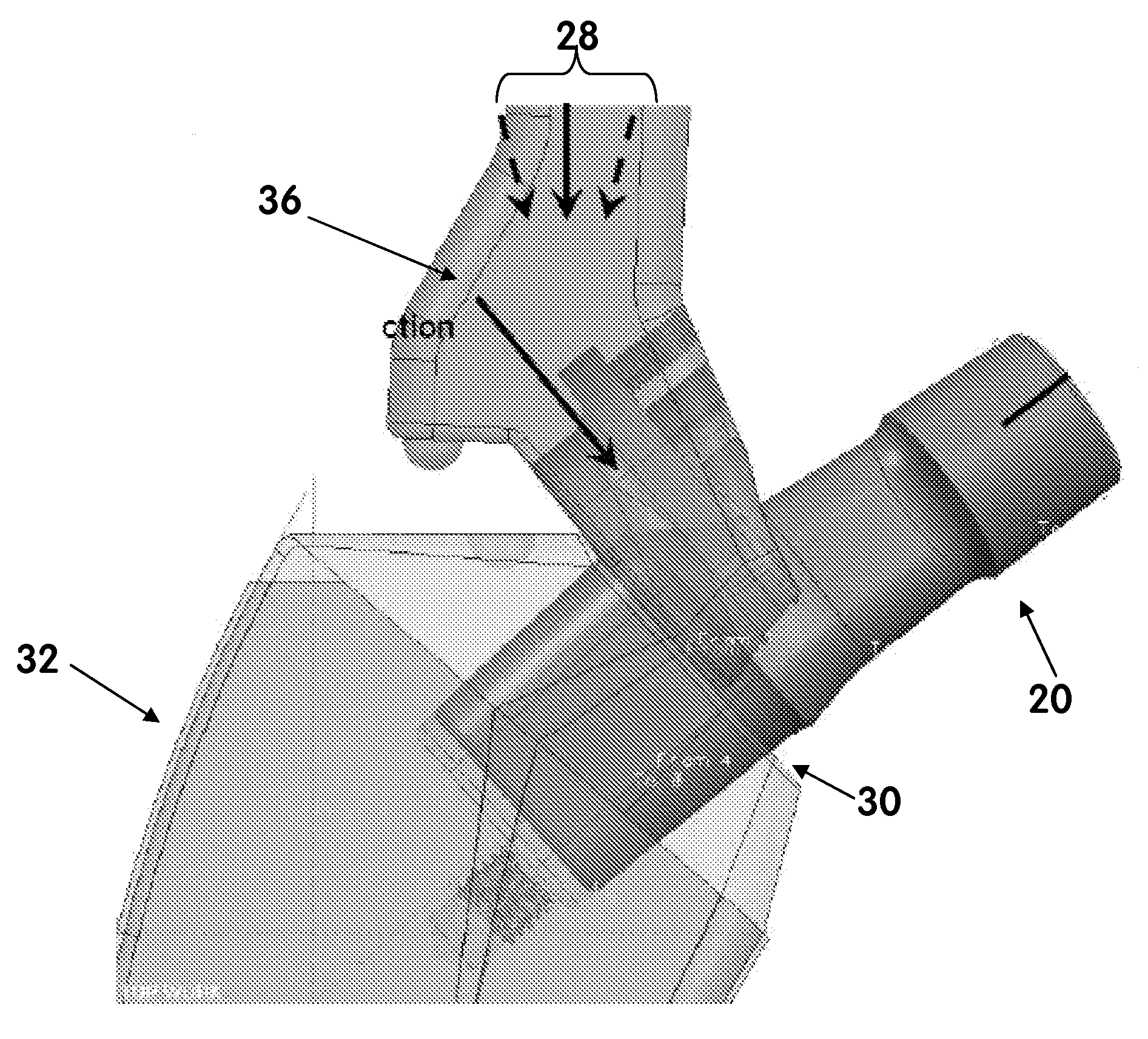
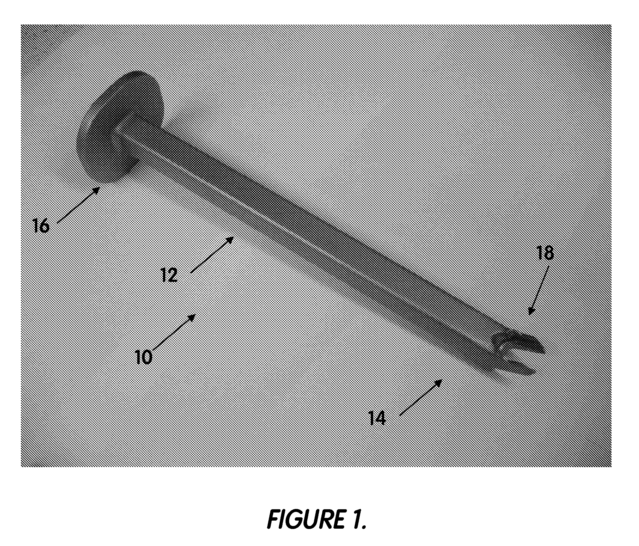
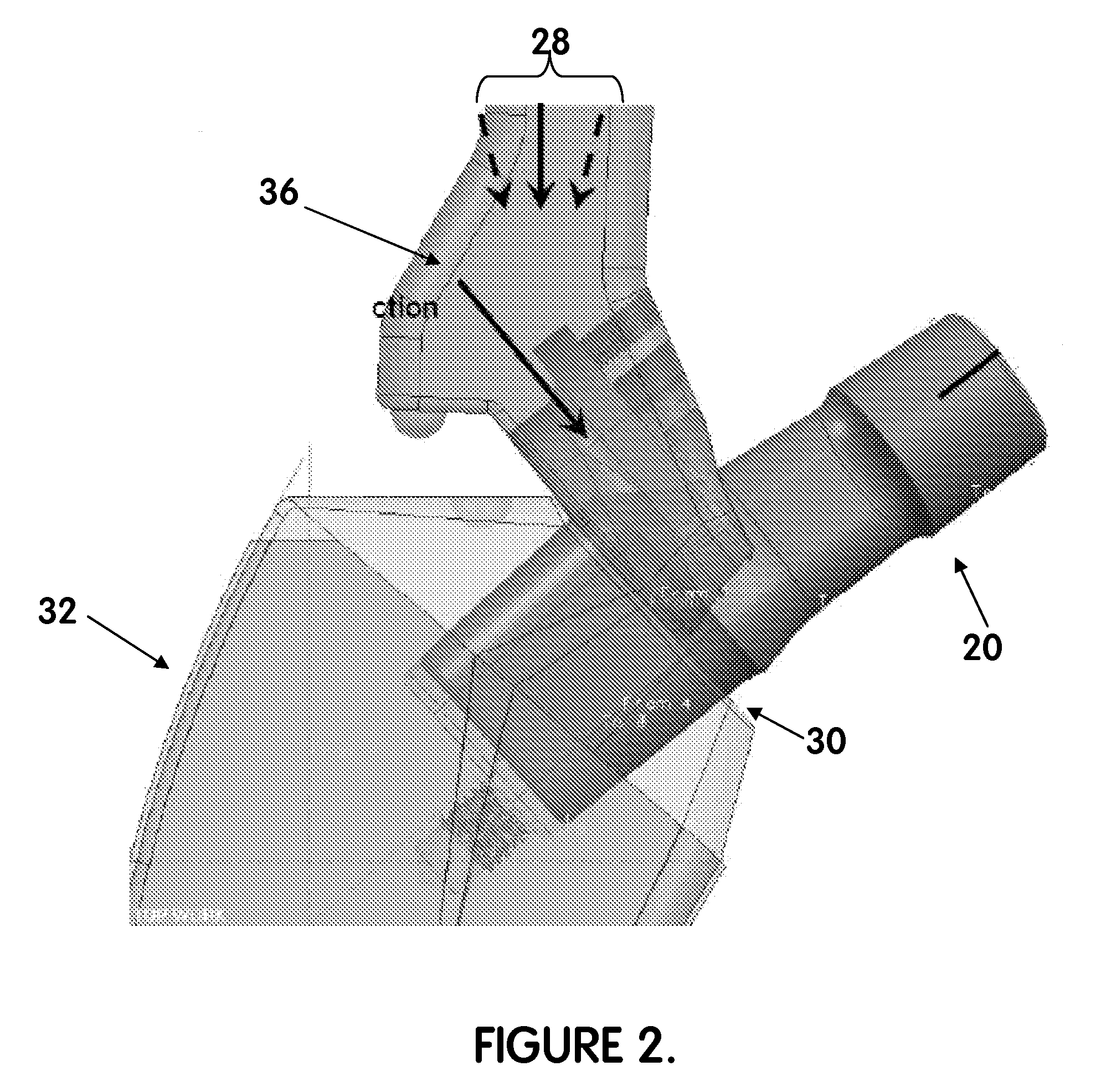
[0046]Referring to the accompanying drawings in which like reference numbers indicate like elements, FIGS. 1 through 7 illustrate a neck extractor 10. The neck extractor 10 generally comprises an elongated neck extractor shank 12 having a bi-forked distal end 14 and a blunt proximal end 16. The bi-forked distal end 16 may have projections 18 configured to extend from the shank 12 to grasp a neck implant 20 (FIG. 2).

[0047]The bi-forked distal end 14 preferably comprises a wedge shaped when viewed in a side profile. However, the bi-forked end 14 may also comprise a curved or flattened shape when viewed in a side profile. Such shape may be beneficial in inserting the forked end around the neck 20.

[0048]Preferably, the inside surface of each extending projection 18 comprises a uniform radius or chamfer. However, the radius / chamfer may vary or “grow” in a direction from a projection 18 toward the elongated shank 12 to enhance “wedging”. The inside surfaces of each finger may be closer to...


PUM


Abstract

Instrumentation for a modular prosthesis having a stem and a neck comprises a handle and an adaptor. The handle extends along an axis. The handle has a distal end and a proximal end. The proximal end has a blunt surface configured to be struck. The adaptor has a male end configured to mate inside the bore of the stem. The adaptor further has a surface configured to mate with the distal end of the handle. The adaptor is configured to have a medial portion and a lateral portion. The medial portion has a relief such that the adaptor is configured to disengage the stem when the adaptor is rotated relative the stem.

Description

CROSS-REFERENCE TO RELATED APPLICATIONS[0001]This application claims the benefit of U.S. Provisional Application No. 61 / 079,011, filed Jul. 8, 2008. The disclosure of each application is incorporated by reference in its entirety.BACKGROUND OF THE INVENTION[0002]1. Field of the Invention[0003]This invention relates generally to minimally invasive surgical tools for hip prostheses and, more particularly, to surgical tools for modular hip prostheses.[0004]2. Related Art[0005]Currently, there is a need to reduce surgical time and provide less-invasive means for implanting surgical devices. In particular, there is a need for improved instrumentation for hip stems which use modular-style necks. There is also a need to trial from a postless broach that uses modular-style necks. There currently exists a challenge in allowing the broach to be properly inserted and extracted under great forces without the use of a conventional “post” or “locking shank”. To date, it is believed that the only m...

Claims


Application Information

Patent Timeline
Patent Type & Authority Applications(United States)
IPC IPC(8): A61F2/38A61B17/56
CPCA61F2/4607A61F2/4637A61F2002/30604A61F2002/4628A61F2002/4619A61F2002/4629A61F2002/4641A61F2002/3652
Inventor GIBSON, LUKE ANDREWWALTERSDORFF, WILLIAM L.
Owner SMITH & NEPHEW INC
Learn More