Marine vessel navigation device, system and method

a navigation device and navigation system technology, applied in the field of marine electronic devices, can solve problems such as difficulty in reading, using, and/or understanding, and achieve the effect of reducing false alarms

Active Publication Date: 2012-11-15
GARMIN
View PDF17 Cites 42 Cited by
  • Summary
  • Abstract
  • Description
  • Claims
  • Application Information

AI Technical Summary

Benefits of technology

[0007]In another embodiment, the processing system is operable for causing the display to display a lane which indicates a desired route between an origination point and a destination. The lane has boundaries which indicate acceptable and non-acceptable course deviations from the desired route. The width of the lane may be selected by an operator or may be automatically determined based on vessel data such as the current speed, heading, or turning radius of the vessel. The use of a lane with boundaries to designate a desired route accommodates for minor drifting, turning, or other course deviations which are expected for marine vessels. As with the previous embodiment, the processing system may also cause the display to display a guidance indicator, such as an arrow, to guide the vessel back within the lane whenever the vessel veers off course.
[0011]In another embodiment, the processing system is operable for causing the display to display a marine map and a radar image overlaid on the map. The marine electronic device of this embodiment also includes a single control (e.g., a dedicated button, touch-screen menu item, etc.) which adjusts both the scale of the map and the range of the radar image. The single control eliminates the need for two separate scale and range controls. In one embodiment, the single range / scale control simultaneously adjusts the radar range and the map scale when the vessel position marker is centered on the display but only adjusts the map scale when the vessel position marker is not centered in the display (for example, when panning the map).
[0015]In another embodiment, the processing system is operable for causing the display to display a three-dimensional (3D) map page and for determining an optimal vertical exaggeration factor for the 3D map page. The processing system uses a variable exaggeration for each point on the terrain triangle mesh using two factors. The first is that elevation exaggeration for each point varies with distance from the elevation of the water surface. Elevations near the water surface are exaggerated less than elevations farther away from the water surface. The second is that points that fall within the water areas cannot have elevations greater than the water surface. The reason behind these two methods is to prevent water areas drawing at higher elevations than they should due to differences between our elevation data and water area data.
[0016]In another embodiment, the processing system is operable for smoothly adjusting both the camera position and camera angle of the three-dimensional map display. The camera position and camera angle may be adjusted in such a way as to maintain the current position marker for the vessel in the same area on the display as the camera position and camera angle are changed. The user adjusts the camera position and the processing system then automatically adjusts the camera angle so that the point of focus (the vessel or the bottom under the vessel) is always placed in the same area of the screen. This feature may be provided for both aerial views and underwater views.
[0019]In another embodiment, the processing system is operable for creating a guard zone around a vessel in which the device is used for identifying threats to the vessel (e.g. other boats, buoys, docks, obstructions, etc.). The guard zone can be automatically adjusted to account for nearby objects which are not currently a threat to reduce false alarms and to shift processing power to possible real threats.

Problems solved by technology

Unfortunately, existing chartplotters and other marine electronic devices often display navigational-related information and other information in such a way that makes it difficult to read, use, and / or interpret.

Method used


Image

  • Marine vessel navigation device, system and method
  • Marine vessel navigation device, system and method
  • Marine vessel navigation device, system and method

Examples


Embodiment Construction

[0063]The following detailed description references the accompanying drawings that illustrate specific embodiments in which the invention can be practiced. The embodiments are intended to describe aspects of the invention in sufficient detail to enable those skilled in the art to practice the invention. Other embodiments can be utilized and changes can be made without departing from the scope of the present invention. The following detailed description is, therefore, not to be taken in a limiting sense. The scope of the present invention is defined only by the appended claims, along with the full scope of equivalents to which such claims are entitled.

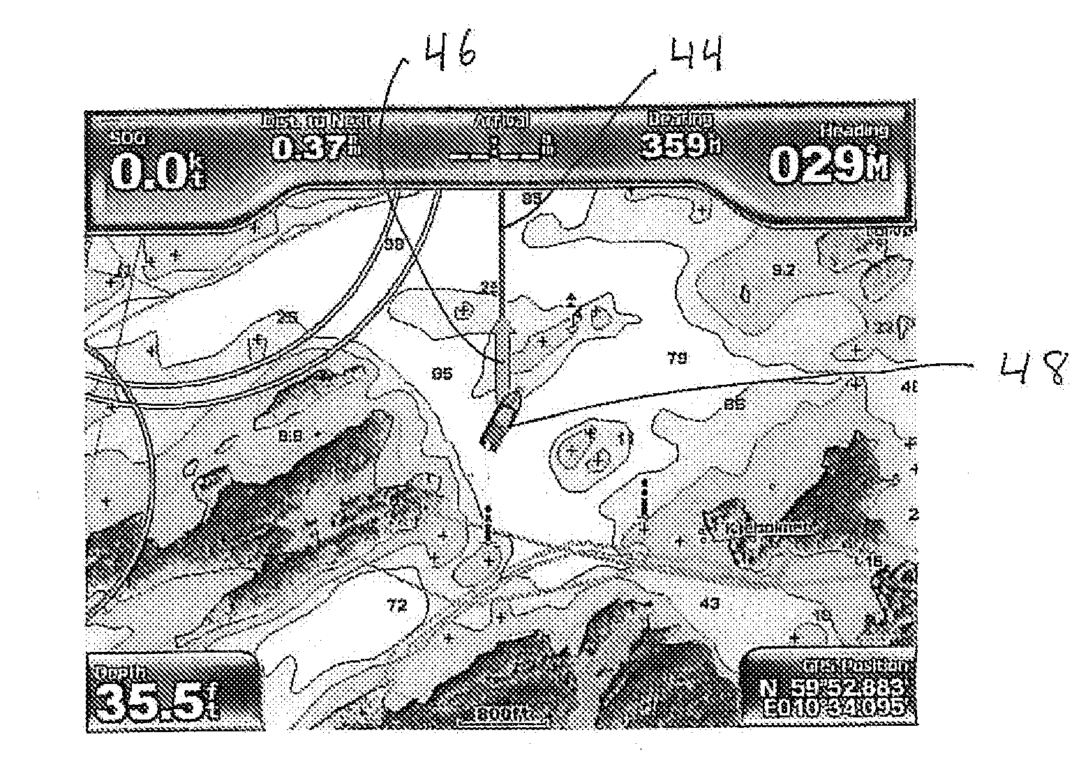
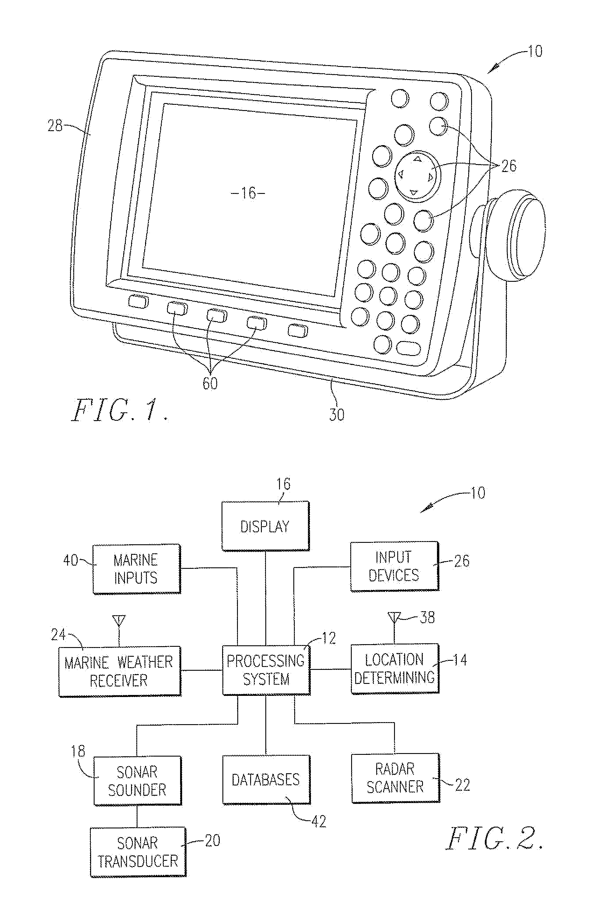
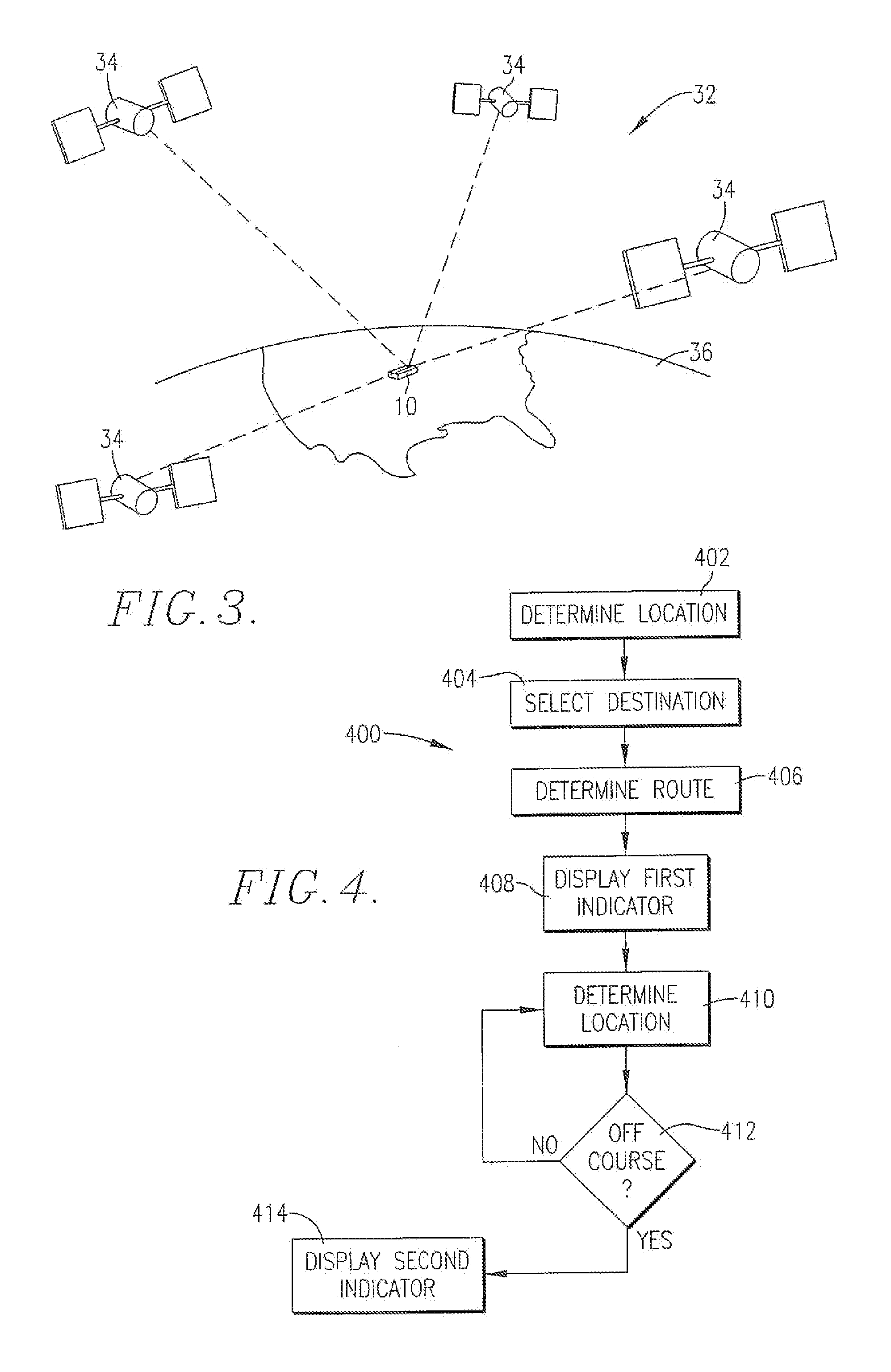
[0064]The present invention can be implemented in hardware, software, firmware, or a combination thereof. In an exemplary embodiment, the invention is implemented with a marine electronic device 10 such as the one illustrated in FIG. 1. The marine electronic device 10 may be any device which provides navigational-related information to ...


PUM


Abstract

A marine electronic device such as a chartplotter which includes a display; a location determining component; and a processing system for receiving location data from the location determining component and for causing information to be displayed by display. The processing system causes the display to display information which assists an operator in navigating and ascertaining characteristics of bodies of water, objects on nearby shores, and other vessels.

Description

CROSS-REFERENCE TO RELATED APPLICATIONS[0001]The present application is a continuation of, and claims priority benefit to, co-pending and commonly assigned U.S. patent application entitled “MARINE VESSEL NAVIGATION DEVICE, SYSTEM AND METHOD,” application Ser. No. 11 / 801,138, filed May 9, 2007, which in turn claims the benefit, under 35 U.S.C. §119(e), of U.S. Provisional Application No. 60 / 865,599, entitled “SYSTEM AND METHOD FOR MARINE AUTO-GUIDANCE,” filed Nov. 13, 2006. Each of the above-identified applications is incorporated herein by reference in its entirety.BACKGROUND[0002]1. Field[0003]The present invention relates to marine electronic devices such as chartplotters and the like, and, more particularly, to improved devices, systems and methods for displaying navigation-related information on a chartplotter or other marine electronic device.[0004]2. Description of the Related Art[0005]Chartplotters and other marine electronic devices are commonly used by boaters to view carto...

Claims


Application Information

Patent Timeline
Patent Type & Authority Applications(United States)
IPC IPC(8): G01C21/00G09G5/00
CPCG01C21/22G08G3/02
Inventor KABEL, DARRIN W.HAIN, DARREN E.WILBECK, BRAYDEN S.BILDERBACK, CHRISTOPHER B.
Owner GARMIN
Why Eureka
Try Eureka