Fuel pump control apparatus of engine

a technology of control apparatus and fuel pump, which is applied in the direction of electric control, fuel injection apparatus, charge feed system, etc., can solve the problems of wasting current consumption, unable to meet the demand of power saving, and large consumption of self-generated voltage, so as to promote power saving, suppress current consumption, and internal circuit

Active Publication Date: 2012-11-22
MITSUBISHI ELECTRIC CORP
View PDF18 Cites 14 Cited by
  • Summary
  • Abstract
  • Description
  • Claims
  • Application Information

AI Technical Summary

Benefits of technology

[0012]The invention was devised to solve the problems discussed above and has an object to provide a fuel pump control apparatus of an engine that promotes power saving by suppressing current consumption by optimally controlling fuel pump driving duty for a proper amount of fuel to be supplied to an engine according to an amount of fuel consumption corresponding to an operation condition of the engine instead of performing F / B control on a fuel pump driving current and makes an internal circuit of an ECU simpler by enhancing fuel supply accuracy.

Problems solved by technology

Accordingly, because a larger driving amount has to be provided to the fuel pump, a wasteful loss occurs in current consumption and a self-generated voltage is consumed considerably.
The proposed method therefore has a problem that it does not match up with the demand of power saving.
In addition, because an amount of fuel to be supplied to the engine by the fuel pump is determined according to data pre-set in the ECU, it is difficult to adjust an amount of fuel by quickly responding to irregularities among parts involved with an actuator and a change of the engine condition.
Hence, accuracy above a certain degree cannot be achieved with a unique map value.
Further, because a current obtained by power generation is consumed by a load on the fuel pump when a larger driving amount than is essentially necessary is set in driving duty data, the power generator attached to the fuel supply apparatus has to have a large generation capacity.
Moreover, a temperature of the motor itself rises due to current consumption by the fuel pump and the parts undergo a temperature-induced drift.
This results in a problem that even when the fuel pump is driven by the same driving amount, because motor rotations differ from pump characteristics of the driving duty, the same result cannot be obtained.
In this case, it is necessary to set the data system by system and there arises a problem that man-hours are increased to make fuel pump apparatus available for another engine.Patent Document 1: JP-A-11-247695

Method used


Image

  • Fuel pump control apparatus of engine
  • Fuel pump control apparatus of engine
  • Fuel pump control apparatus of engine

Examples


first embodiment

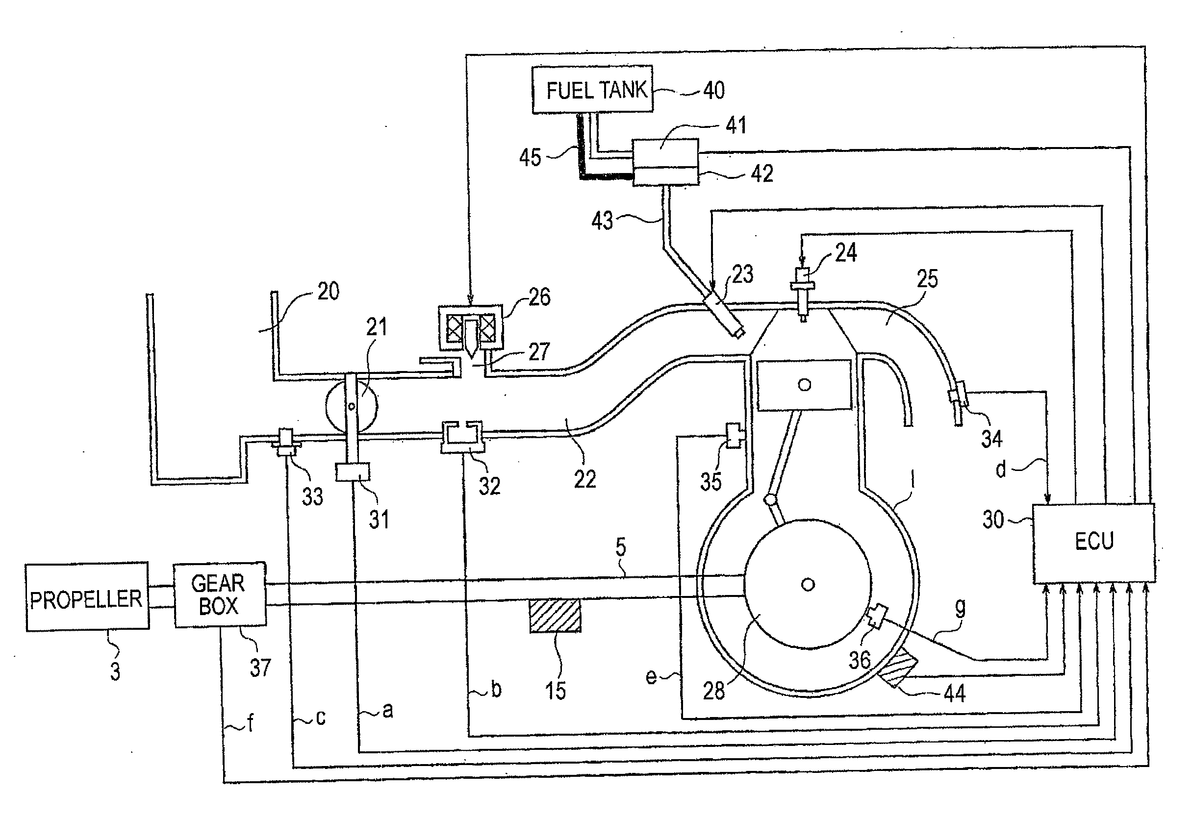
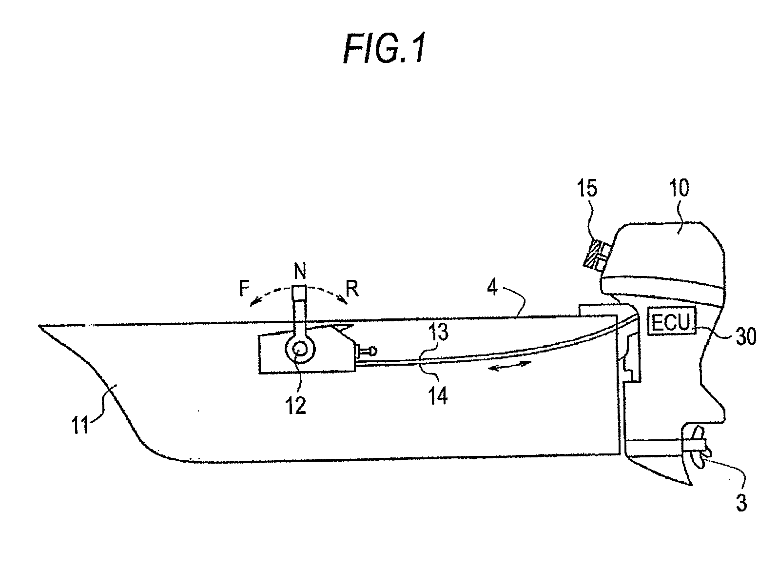
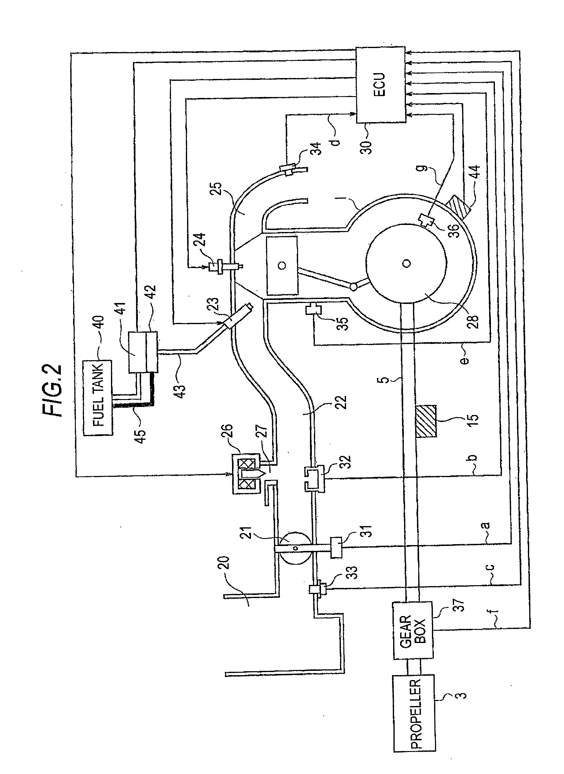
[0027]FIG. 1 is a view showing the overall configuration when the invention is applied to an internal combustion engine for ship. An outboard motor 10 having an internal combustion engine (hereinafter, referred to as the engine), a shaft, and a propeller 3 provided integrally in one unit includes an ECU (Electronic Control Unit) 30 as a controller and is attached at the stern of a ship (small boat) 11.

[0028]A throttle lever 12 is disposed at a pilot seat 4. The throttle lever 12 regulates an amount of aperture of a throttle valve (an amount of intake air) by way of a link mechanism (not shown) in the outboard motor 10 via a throttle cable 13. The throttle lever 12 also sets a shift position (forward / neutral / reverse) by way of a shift link mechanism and a gear mechanism (neither is shown) in the outboard motor 10 via a shift cable 14. A recoil starting device 15 that gets the engine started manually is attached to the outboard motor 10. The engine furnished with neither a battery nor...


PUM


Abstract

By driving a fuel pump suitably to an amount of fuel according to an amount of fuel consumed by an engine and by monitoring an actual motor speed of the fuel pump, F/B control is carried out according to a target motor speed and the actual motor speed of the fuel pump. Meanwhile, by learning and storing a duty value comparable to a deviation between the target and actual motor speeds, duty driving of the fuel pump is corrected to suit an engine condition. It thus becomes possible to provide a fuel pump control apparatus of an engine capable of promoting power saving by suppressing a wasteful energy loss including a current consumption and making an internal circuit of an ECU simpler by enhancing fuel supply accuracy.

Description

BACKGROUND OF THE INVENTION[0001]1. Field of the Invention[0002]The present invention relates to a fuel pump control apparatus of an engine, and more particularly, to a fuel pump control apparatus of an engine for small outboard motor unfurnished with a battery and getting the engine started by manually rotating a crank shaft.[0003]2. Background Art[0004]For an outboard motor for small boat having a relatively small displacement, a carburetor system is the mainstream of a fuel supply. An outboard motor adopts a device configuration furnished with neither a battery nor a starter and thereby getting the engine started by a manual operation of a ship operator using a recoil starting device, that is, a typical outboard motor is relatively lightweight and gets the engine started at a low cost. However, with the aim of enhancing ease of operation and maintenance, emission control, and output performance, shifting from the carburetor system to an FI (Fuel Injection) system is taking place ...

Claims


Application Information

Patent Timeline
Patent Type & Authority Applications(United States)
IPC IPC(8): F02M59/00
CPCF02D41/2464F02D2041/2027F02D41/3082
Inventor YAMAGUCHI, YOHEIISHIDA, YASUHIKO
Owner MITSUBISHI ELECTRIC CORP
Why Eureka
Try Eureka