Systems and methods for reuse of battery pack-side current and voltage sensing

a battery pack and current sensing technology, applied in the field of controlling battery charging, can solve the problems of increasing the power consumption that such functionality requires, and achieve the effects of reducing impedance, promoting power saving, and eliminating battery

Active Publication Date: 2019-12-17
QUALCOMM INC
View PDF17 Cites 0 Cited by
  • Summary
  • Abstract
  • Description
  • Claims
  • Application Information

AI Technical Summary

Benefits of technology

[0007]Aspects disclosed in the detailed description include systems and methods for reuse of battery pack-side current and voltage sensing. By reusing elements within a battery pack, a battery field effect transistor (FET) within a power management integrated circuit (PMIC) may be eliminated or at least bypassed. Removal of the battery FET in the PMIC from a charging path substantially reduces impedance, which promotes power savings. Elimination of the battery FET from the PMIC allows for space savings commensurate with the relatively large size of the battery FET as well as cost savings. In a first aspect, a current mirror is coupled to a charge protection circuit in the battery pack to capture a sensed current. Likewise, a voltage sensor captures a voltage level for the charging path. Current and voltage are output to the PMIC for use in regulating a buck charger. In a second aspect, current data and voltage data are collected and digitized before being sent to the PMIC for use in regulating the buck charger.

Problems solved by technology

Such increased processing power is offset in part by the increased power consumption that such functionality requires.

Method used


Image

  • Systems and methods for reuse of battery pack-side current and voltage sensing
  • Systems and methods for reuse of battery pack-side current and voltage sensing
  • Systems and methods for reuse of battery pack-side current and voltage sensing

Examples


Embodiment Construction

[0019]With reference now to the drawing figures, several exemplary aspects of the present disclosure are described. The word “exemplary” is used herein to mean “serving as an example, instance, or illustration.” Any aspect described herein as “exemplary” is not necessarily to be construed as preferred or advantageous over other aspects.

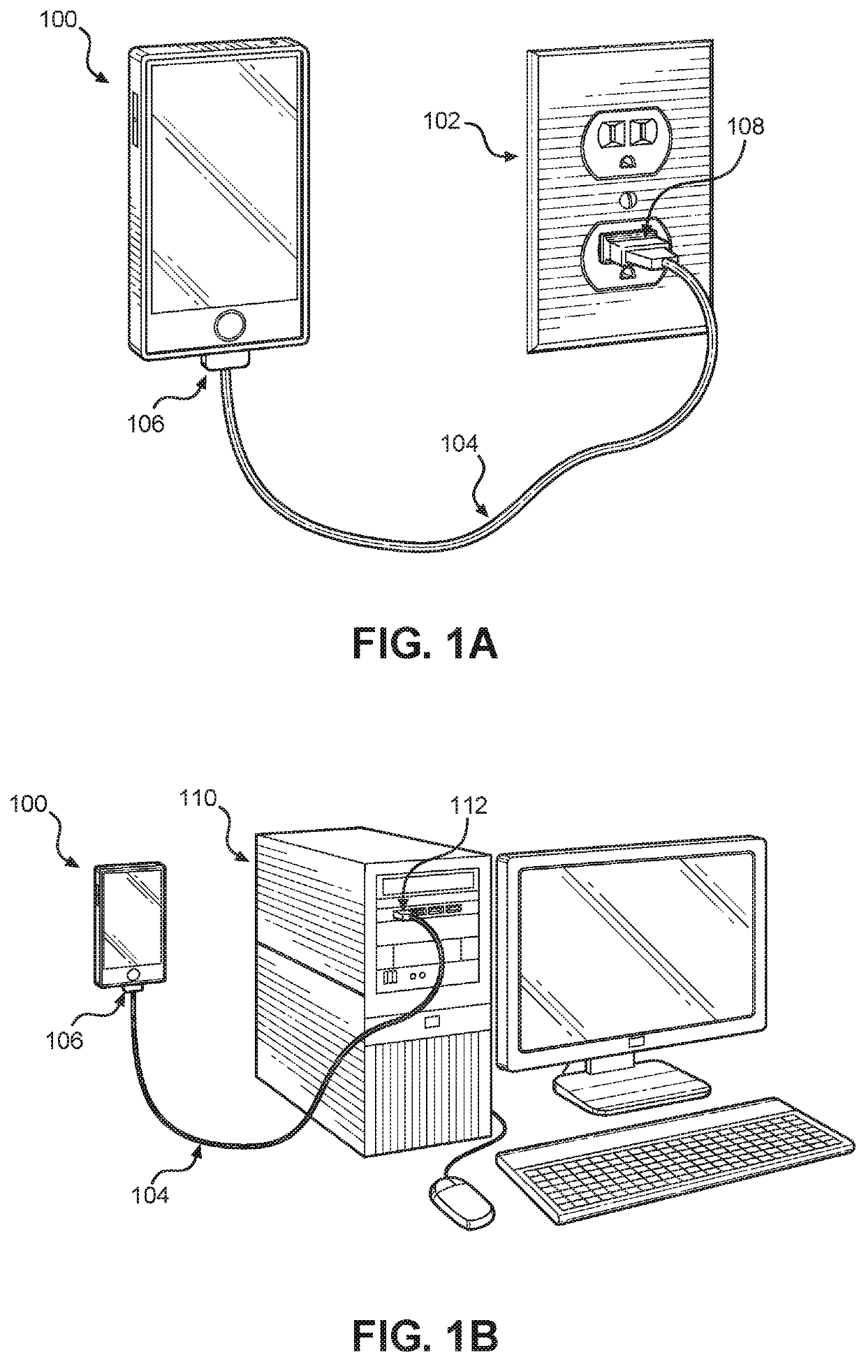
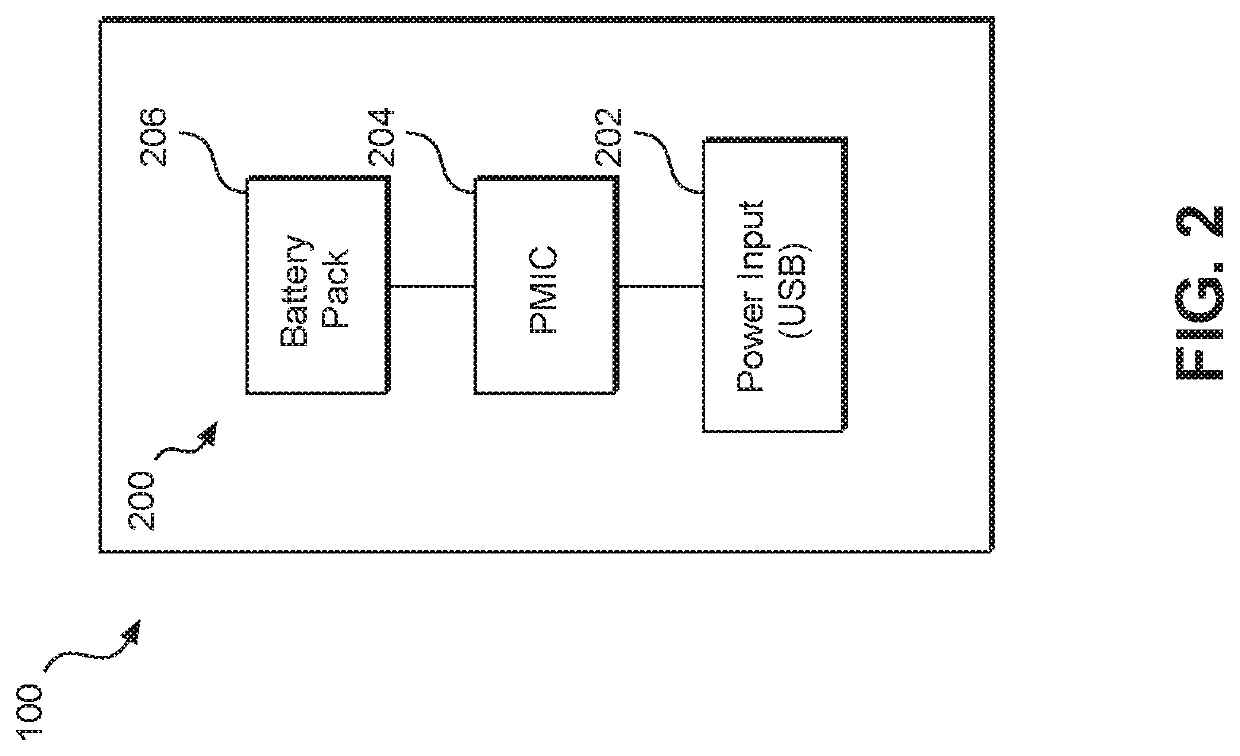
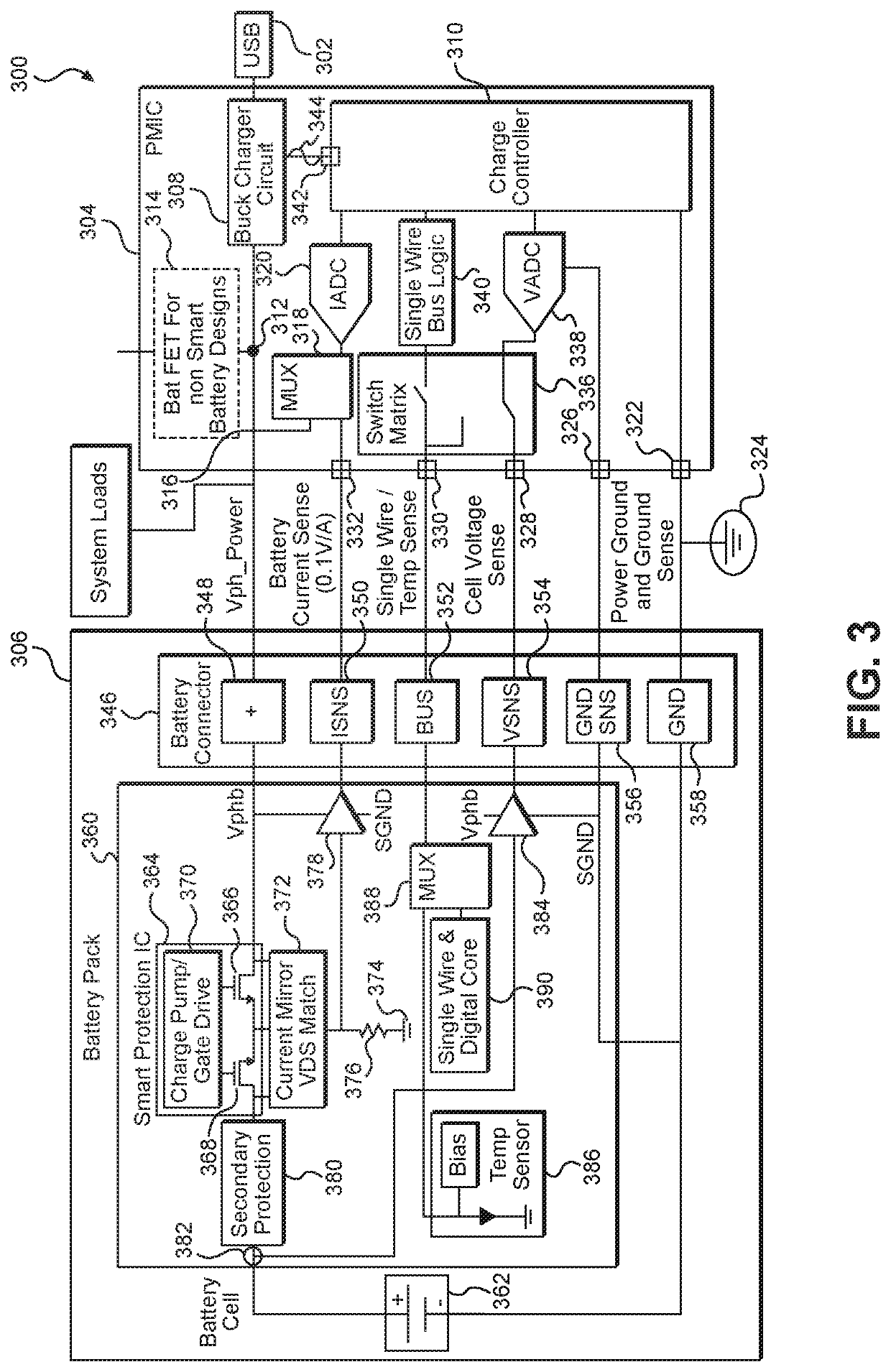
[0020]Aspects disclosed in the detailed description include systems and methods for reuse of battery pack-side current and voltage sensing. By reusing elements within a battery pack, a battery field effect transistor (FET) within a power management integrated circuit (PMIC) may be eliminated or at least bypassed. Removal of the battery FET in the PMIC from a charging path substantially reduces impedance, which promotes power savings. Elimination of the battery FET from the PMIC allows for space savings commensurate with the relatively large size of the battery FET as well as cost savings. In a first aspect, a current mirror is coupled to a charge prot...


PUM

PropertyMeasurementUnit
currentaaaaaaaaaa
voltageaaaaaaaaaa
digital currentaaaaaaaaaa

Abstract

Systems and methods for reuse of battery pack-side current and voltage sensing are disclosed. By reusing elements within a battery pack, a battery field effect transistor (FET) within a power management integrated circuit (PMIC) may be eliminated or at least bypassed. In a first aspect, a current mirror is coupled to a charge protection circuit in the battery pack to capture a sensed current. Likewise, a voltage sensor captures a voltage level for a charging path. Current and voltage are output to the PMIC for use in regulating a buck charger. In a second aspect, current data and voltage data are collected and digitized before being sent to the PMIC for use in regulating the buck charger.

Description

BACKGROUND[0001]I. Field of the Disclosure[0002]The technology of the disclosure relates generally to controlling battery charging in mobile computing devices.[0003]II. Background[0004]Mobile computing devices have become increasingly common throughout society. The proliferation of such mobile computing devices is fueled in part by increased processing power that enables increased functionality. Such increased processing power is offset in part by the increased power consumption that such functionality requires. Concurrent with the increased functionality, advances have been made in batteries such that the time that passes before a battery needs to be recharged has been extended (sometimes referred to as battery run time). Likewise, the time required to charge a battery has been reduced.[0005]There are generally two components used in charging a battery. The first component is a battery pack, which may include, in addition to the actual battery, charge protection circuitry and a tem...

Claims


Application Information

Patent Timeline
Patent Type & Authority Patents(United States)
IPC IPC(8): H02J7/00H01M10/42H01M10/48H01M50/574
CPCH01M10/425H02J7/007H02J7/0044H01M10/48H02J7/0026H01M2220/30H01M10/486H01M2010/4271H01M2010/4278H01M10/44H01M2200/00H02J7/00H01M10/4257Y02E60/10H01M50/574
Inventor OIKARINEN, JUHASPORCK, CHRISTIAN GREGORY
Owner QUALCOMM INC
Why Eureka
Try Eureka