Systems and Methods of RF Power Transmission, Modulation, and Amplification, Including Varying Weights of Control Signals

a technology of power transmission and modulation, applied in the field of rf (radio frequency) power transmission, modulation, amplification, can solve the problems of low power amplifier efficiency, degradation of output signal power, and inapplicability of existing outphasing techniques in modern portable devices

Inactive Publication Date: 2012-11-22
PARKER VISION INC
View PDF7 Cites 23 Cited by
  • Summary
  • Abstract
  • Description
  • Claims
  • Application Information

AI Technical Summary

Problems solved by technology

In several respects, however, existing outphasing techniques are not suitable for implementation in modern portable devices.
For example, the isolating and / or combining element that they use causes a degradation in output signal power (due to insertion loss and limited bandwidth) and, correspondingly, low power amplifier efficiency.
Further, the typically large size of isolating / combining elements precludes having them in monolithic amplifier designs.

Method used


Image

  • Systems and Methods of RF Power Transmission, Modulation, and Amplification, Including Varying Weights of Control Signals
  • Systems and Methods of RF Power Transmission, Modulation, and Amplification, Including Varying Weights of Control Signals
  • Systems and Methods of RF Power Transmission, Modulation, and Amplification, Including Varying Weights of Control Signals

Examples


Embodiment Construction

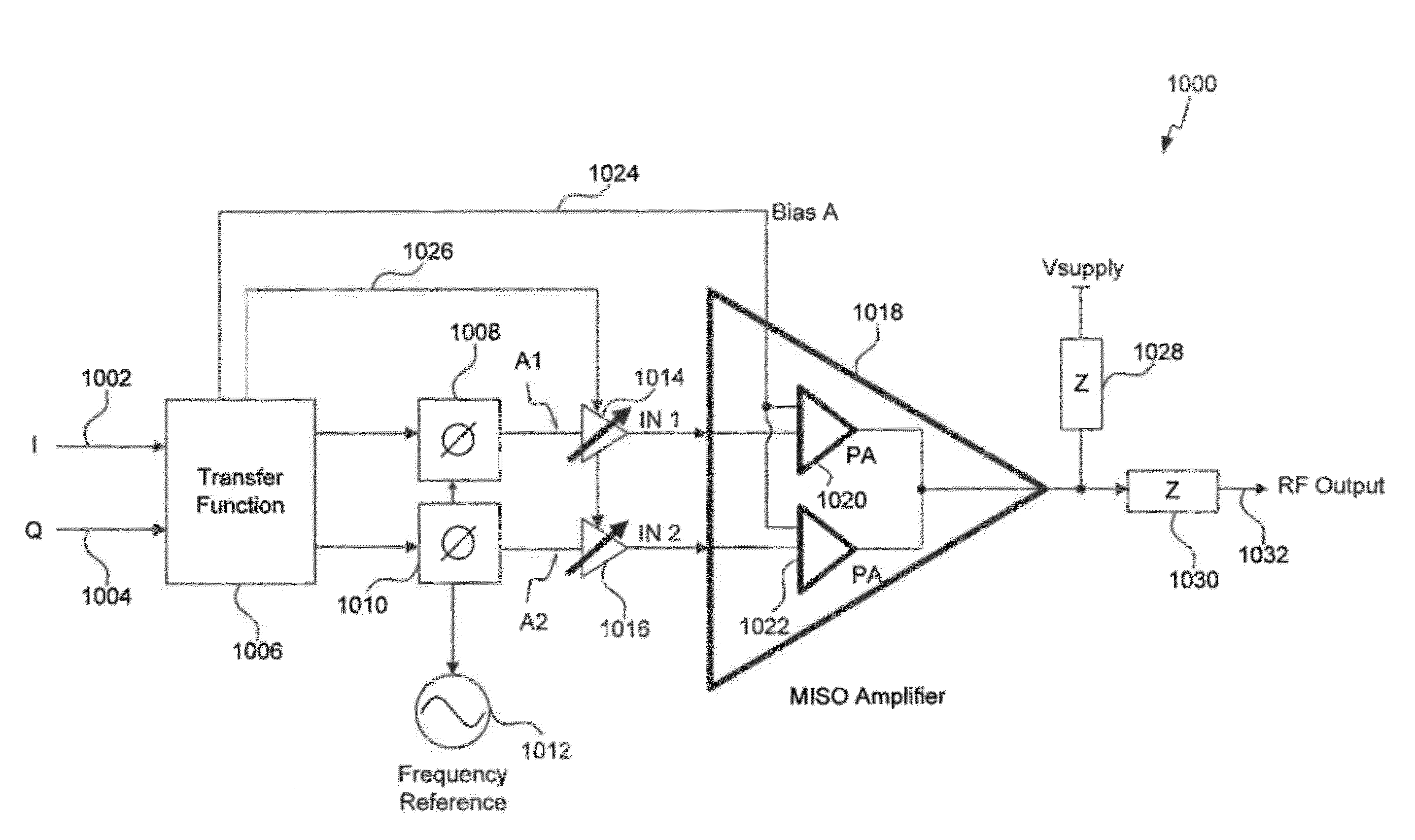
[0038]In commonly owned U.S. patent(s) and application(s), cross-referenced above, VPA (Vector Power Amplification) and MISO (Multiple-Input-Single-Output) amplification embodiments were introduced. VPA and MISO provide combiner-less RF power amplification, which results in high power amplifier efficiency. At the same time, despite minimal or zero branch isolation, VPA and MISO amplification include innovative amplifier bias functions that effectively result in highly linear amplification over the entire output power range of desired waveforms.

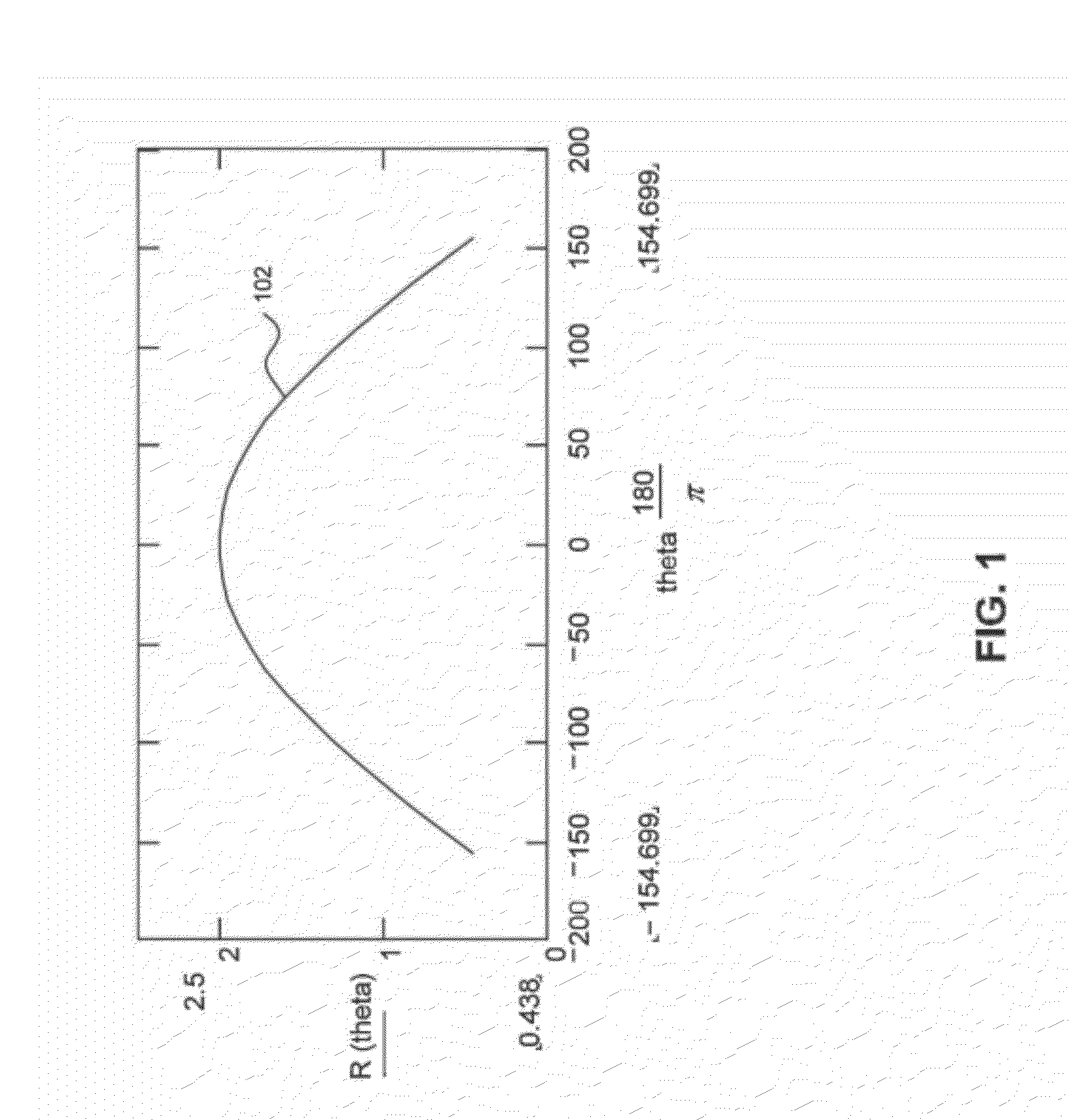
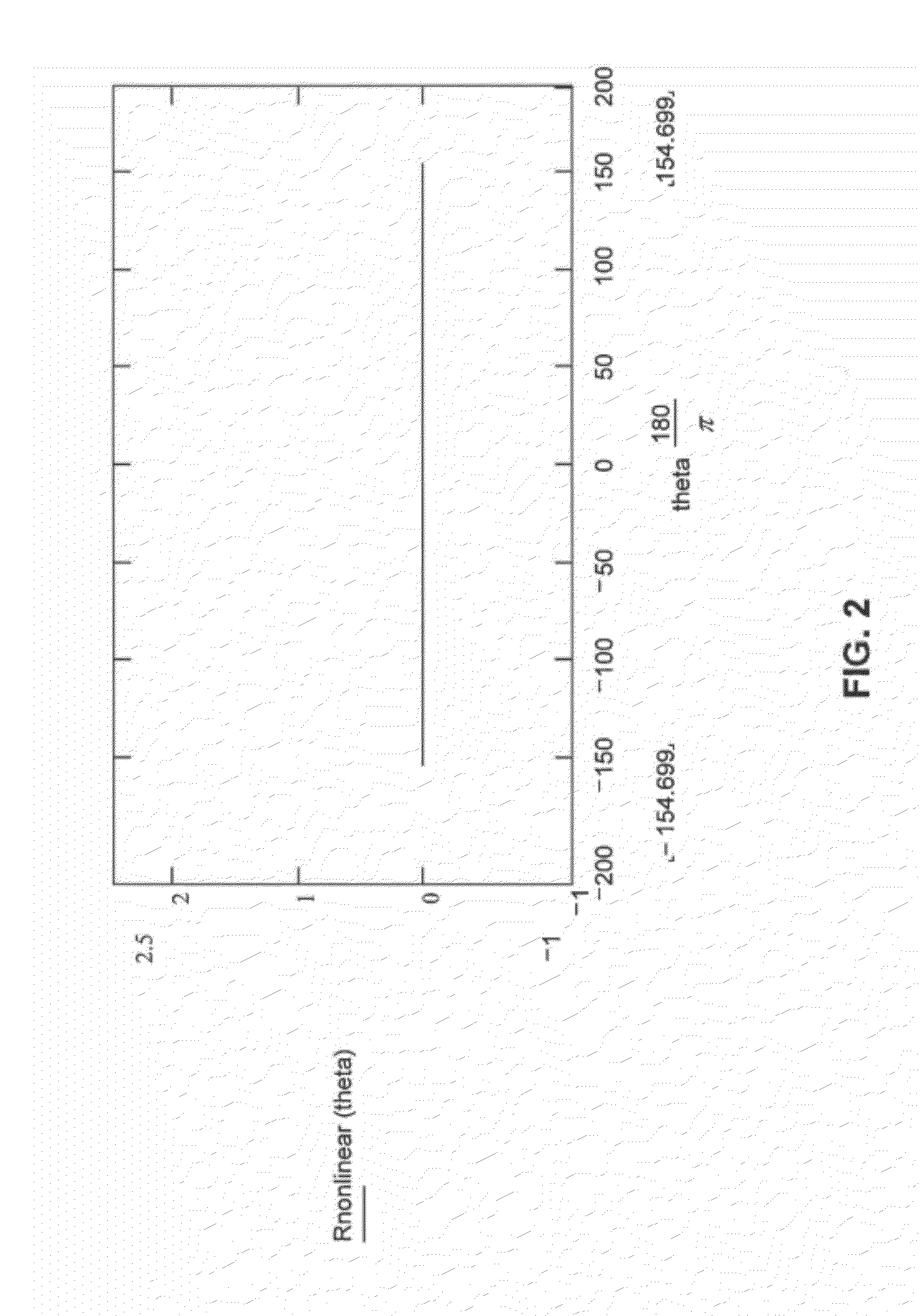
[0039]In the following sections, embodiments of a blended control function for operating a MISO amplifier embodiment are provided. The blended control function allows for the mixing of various output power control functions enabled by VPA and MISO, to generate a desired waveform with high accuracy. In Section 2, the relationship between branch isolation (i.e., isolation between the branches of an outphasing amplifier) and output power error is...


PUM


Abstract

Embodiments of the present invention include a method and system for control of a multiple-input-single output (MISO) device. For example, the method includes determining a change in power output level from a first power output level to a second power output level of the MISO device. The method also includes varying one or more weights associated with respective one or more controls of the MISO device to cause the change in power output. The one or more controls can include one or more of (a) a phase control of one or more input signals to the MISO device, (b) a bias control of the MISO device, and (c) an amplitude control of the input signals to the MISO device

Description

CROSS-REFERENCE TO RELATED APPLICATIONS[0001]The present application is a continuation of U.S. patent application Ser. No. 13 / 069,155, filed Mar. 22, 2011 (Atty. Docket No. 1744.2260001), which is a continuation of U.S. patent application Ser. No. 12 / 236,079, filed Sep. 23, 2008, now U.S. Pat. No. 7,911,272 (Atty. Docket No. 1744.2260000), which is a continuation-in-part of U.S. patent application Ser. No. 12 / 142,521, filed Jun. 19, 2008, now U.S. Pat. No. 8,013,675 (Atty. Docket No. 1744.216000N), which claims the benefit of U.S. Provisional Patent Application No. 60 / 929,239, filed Jun. 19, 2007 (Atty. Docket No. 1744.216000J), and U.S. Provisional Patent Application No. 60 / 929,584, filed Jul. 3, 2007 (Atty. Docket No. 1744.216000L), all of which are incorporated herein by reference in their entireties.[0002]The present application is related to U.S. patent application Ser. No. 11 / 256,172, filed Oct. 24, 2005, now U.S. Pat. No. 7,184,723 (Atty. Docket No. 1744.1900006) and U.S. pat...

Claims


Application Information

Patent Timeline
Patent Type & Authority Applications(United States)
IPC IPC(8): H03F3/68
CPCH03F1/0294H03F3/195H03F3/211H03F2203/21106H03F3/2175H03F2200/451H03F3/213
Inventor SORRELLS, DAVID F.RAWLINS, GREGORY S.
Owner PARKER VISION INC
Why Eureka
Try Eureka