

Image capturing optical lens assembly
a technology of optical lenses and optical components, applied in the field of image capture optical lens assemblies, can solve the problems of inability to produce high-quality images, lens structure requires a longer total optical track length, and insufficient degree of freedom in setting system parameters
- Summary
- Abstract
- Description
- Claims
- Application Information
AI Technical Summary
Benefits of technology
Problems solved by technology
Method used
Image

Examples
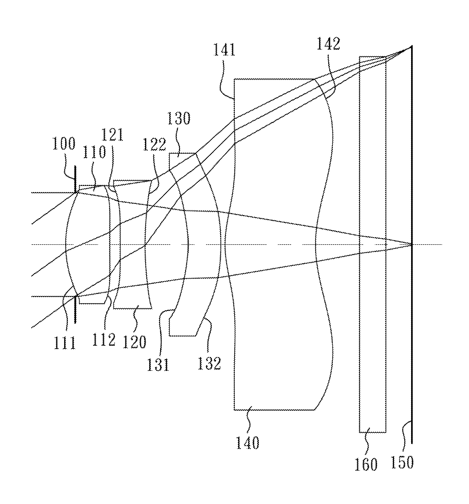
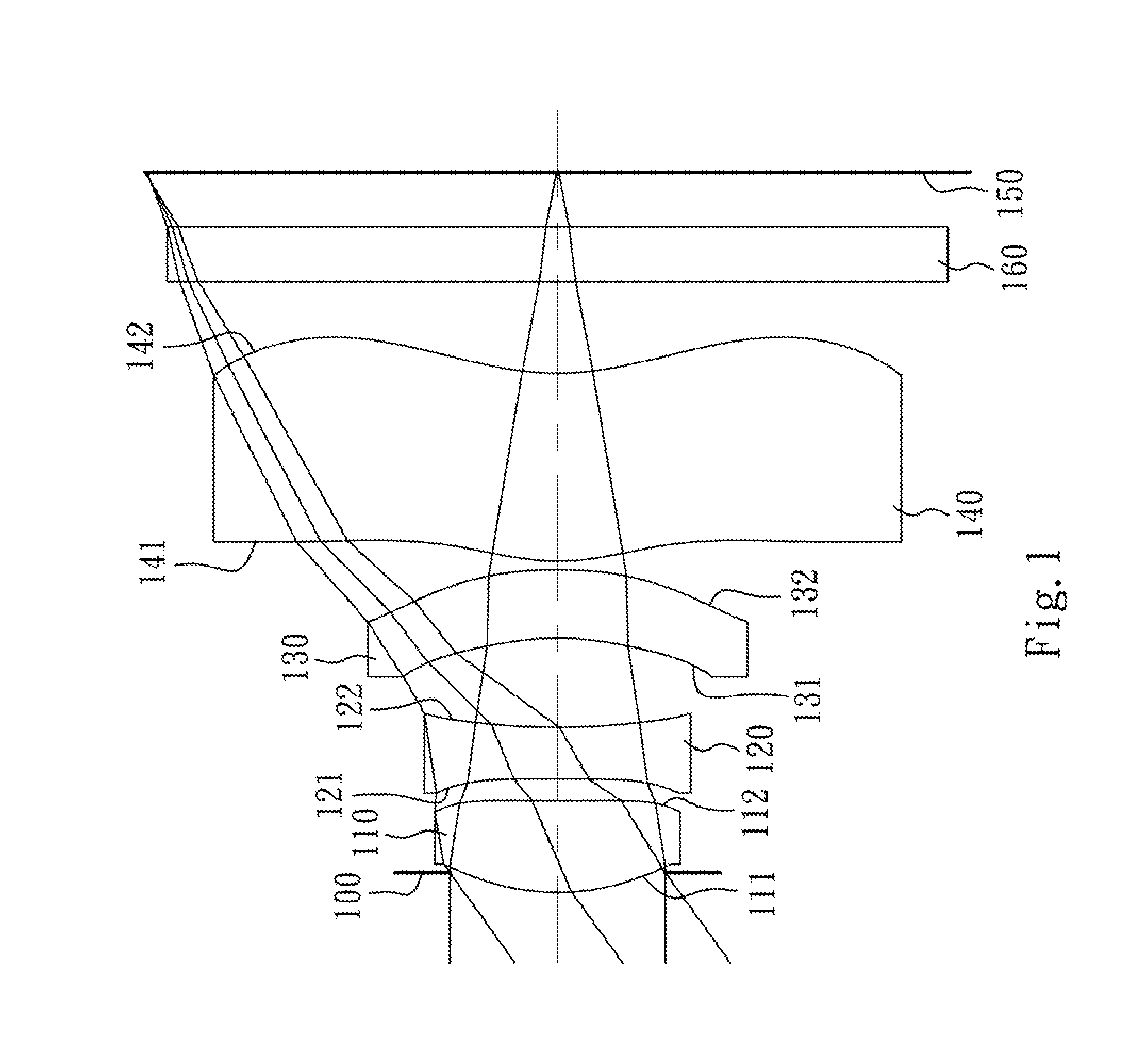
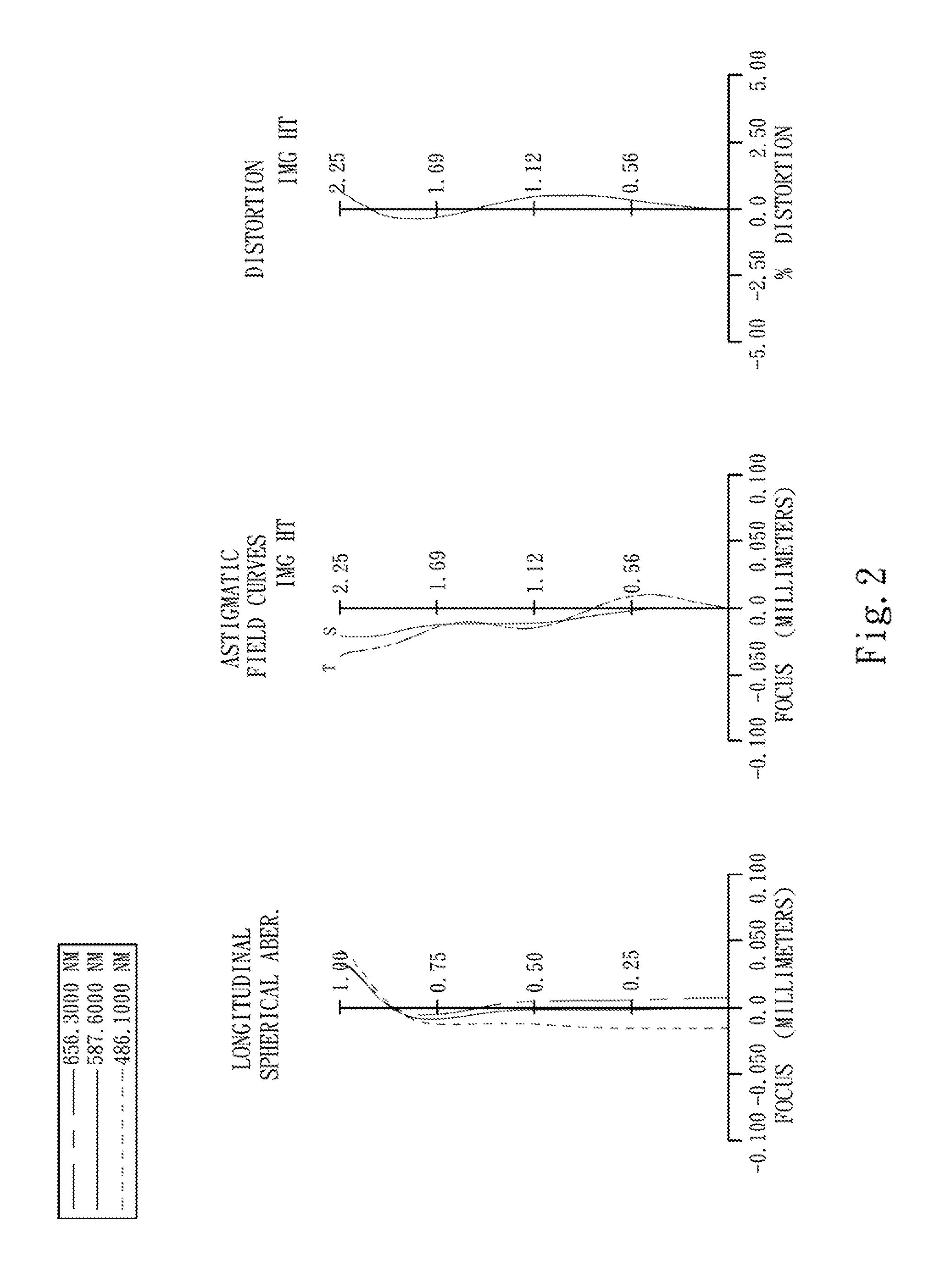
first embodiment
[0058]The equation of the aspheric surface profiles of the aforementioned lens elements of the first embodiment is expressed as follows:
X(Y)=(Y2 / R) / (1+sqrt(1-(1+k)×(Y / R)2))+∑i(Ai)×(Y′)
[0059]where:
[0060]X is the height of a point on the aspheric surface spaced at a distance Y from the optical axis relative to the tangential plane at the aspheric surface vertex;
[0061]Y is the distance from the point on the curve of the aspheric surface to the optical axis;
[0062]R is the curvature radius of the surface of the lens element;
[0063]k is the conic coefficient; and
[0064]Ai is the i-th aspheric coefficient.
[0065]In the image capturing optical lens assembly according to the first embodiment, when f is a focal length of the image capturing optical lens assembly, Fno is an f-number of the image capturing optical lens assembly, and HFOV is half of the maximal field of view, these parameters have the following values:
[0066]f=3.13 mm;
[0067]Fno=2.65; and
[0068]HFOV=35.6 degrees.
[0069]In the image cap...
second embodiment
[0084]The detailed optical data of the second embodiment are shown in Table 3 and the aspheric surface data are shown in Table 4 below.
TABLE 32nd Embodimentf = 3.06 mm, Fno = 2.50, HFOV = 35.6 deg.SurfaceCurvatureFocal#RadiusThicknessMaterialIndexAbbe #length0ObjectPlanoInfinity1Lens 11.315880(ASP)0.488Plastic1.53556.32.9127.447100(ASP)0.0483Ape. StopPlano0.2024Lens 2−11.850200(ASP)0.446Plastic1.65021.4−6.7156.997100(ASP)0.3196Lens 3−1.246240(ASP)0.412Plastic1.53556.3−8.177−1.944390(ASP)0.0508Lens 41.034940(ASP)0.914Plastic1.53556.34.1591.342730(ASP)0.50010IR-filterPlano0.300Glass1.51764.2—11Plano0.37612ImagePlano—Note:Reference wavelength (d-line) is 587.6 nm.
TABLE 4Aspheric CoefficientsSurface #1245k =−6.55534E−01−1.00000E+00−2.44320E+025.00000E+00A4 = 7.30994E−02 2.81554E−02−6.90800E−021.55699E−01A6 =−1.06143E−01−2.66434E−01−5.56765E−01−5.62083E−01 A8 = 5.13352E−01 4.46270E−01 1.11930E+009.05773E−01A10 =−6.54489E−01−8.65305E−01−1.76086E+00−1.00430E+00 A12 =−1.20291E−03−1.66703E−0...
third embodiment
[0093]The detailed optical data of the third embodiment are shown in Table 5 and the aspheric surface data are shown in Table 6 below.
TABLE 53rd Embodimentf = 3.32 mm, Fno = 2.60, HFOV = 33.3 deg.SurfaceCurvatureFocal#RadiusThicknessMaterialIndexAbbe #length0ObjectPlanoInfinity1Lens 11.224110(ASP)0.499Plastic1.53556.32.6727.447100(ASP)0.0413Ape. StopPlano0.2514Lens 2−8.594200(ASP)0.292Plastic1.63423.8−5.2155.432600(ASP)0.3376Lens 3−1.301780(ASP)0.340Plastic1.63423.8−5.477−2.295550(ASP)0.0758Lens 41.015290(ASP)0.747Plastic1.53556.33.6591.575350(ASP)0.50010IR-filterPlano0.300Glass1.51764.2—11Plano0.63012ImagePlano—Note:Reference wavelength (d-line) is 587.6 nm.
TABLE 6Aspheric CoefficientsSurface #1245K =−7.16264E−01−1.00000E+00−1.09884E+025.00000E+00A4 = 7.28466E−02−3.36086E−02−7.32347E−021.63256E−01A6 =−1.55769E−01−5.08219E−02−7.50199E−01−6.47555E−01 A8 = 6.21720E−01−5.13164E−01 1.33756E+008.81400E−01A10 =−8.63411E−01 4.44357E−01−1.05866E+00−6.00338E−01 A12 =−1.19681E−03−9.86714E−07−...
PUM
 Abstract
Description
Claims
Application Information