Flow field plate for reduced pressure drop in coolant

a flow field and coolant technology, applied in the direction of cell components, electrochemical generators, cell component details, etc., can solve the problems of affecting the flow of other fluids in the coolant transition region, non-uniform distribution, and non-uniform sharing, so as to increase the height of the coolant duct, and maintain the overall volume of the stack

Active Publication Date: 2012-11-22
CELLCENTRIC GMBH & CO KG +1
View PDF3 Cites 16 Cited by
  • Summary
  • Abstract
  • Description
  • Claims
  • Application Information

AI Technical Summary

Benefits of technology

[0012]The present invention allows for an increase in coolant duct height, and hence coolant flow rate, in the coolant transition regions of such fuel cell stacks without adversely affecting the flow of the reactants in the coolant transition regions and while maintaining the overall volume of the stack. This can be accomplished by increasing the height of the coolant ducts such that the flow field plate surfaces in the coolant transition region are no longer planar and by accommodating this change by staggering the coolant ducts in adjacent cells and using MEAs which are non-planar in this region.

Problems solved by technology

As will be more apparent when discussing the Figures below, the presence of such ducts can impede the flow of other fluids in the coolant transition region.
This can result in non-uniform distribution to and hence non-uniform sharing of the coolant in the coolant flow field channels in the active area of the fuel cell.
This in turn increases the risk of overheating (hot spots) and over-drying in the cells on hot days.
Also, it can lead to formation of wet spots in the cells, making it difficult to prepare the stack for shutdown in below freezing conditions and also difficult to recover during startup from below freezing conditions.
The pressure drop can be reduced to some extent by sacrificing space provided for the flow of reactants in the coolant transition region but, depending on port and transition designs, this can result in an unacceptable blocking of the flow of one or both of the reactants.
However, the power density of the stack is then undesirably reduced, along with a possible undesirable increase in mass of the stack.

Method used


Image

  • Flow field plate for reduced pressure drop in coolant
  • Flow field plate for reduced pressure drop in coolant
  • Flow field plate for reduced pressure drop in coolant

Examples


example

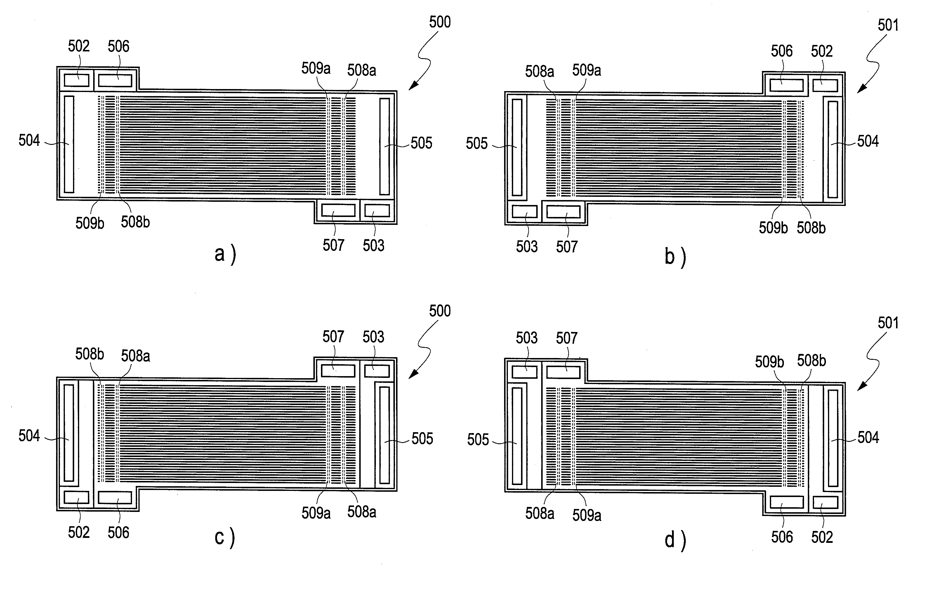
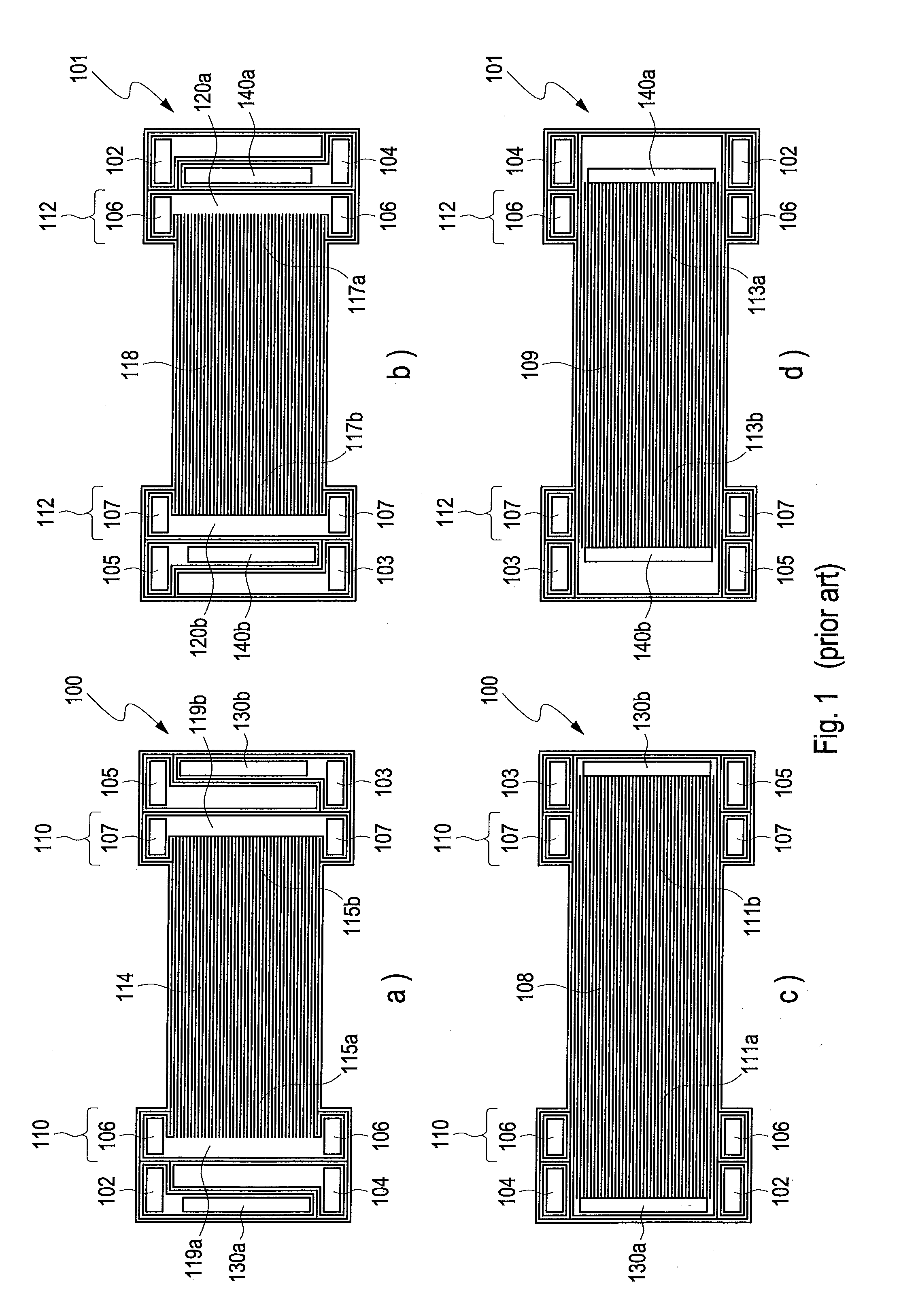
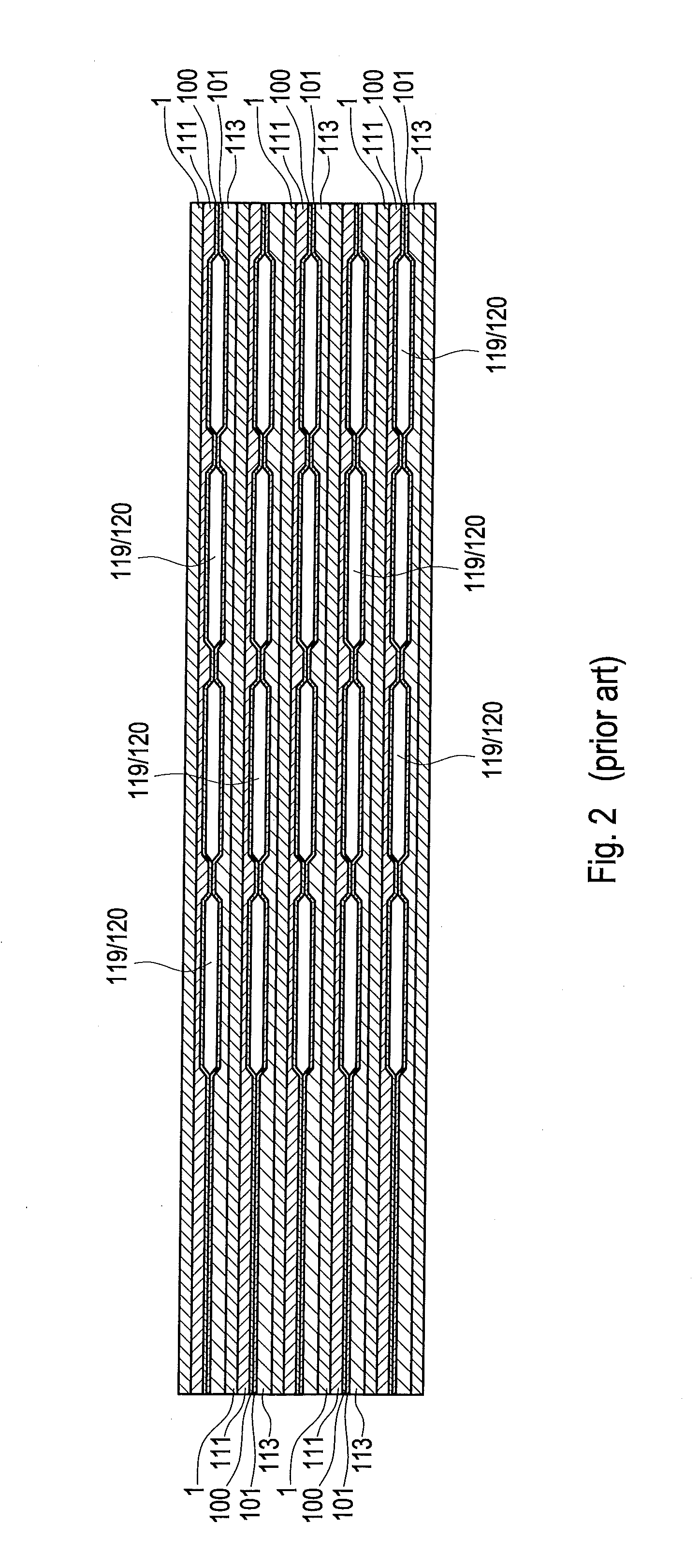
[0049]The coolant pressure drop benefit of an exemplary flow field plate design of the invention was calculated with regards to a fuel cell stack design intended for use in automotive applications. The automotive stack used a plate design similar to that shown in FIGS. 1a, b, c, and d and FIG. 2. The cell pitch in the stack (i.e. cell to cell spacing in the stack) was 1.2 mm. The total height of the closed coolant ducts formed by adjacent, mated anode and cathode plates in the stack was just 3.1 mm high. This allowed for an acceptable total height of 0.25 mm for the closed oxidant transition channels and a height of 0.15 mm for the closed fuel transition channels.

[0050]For comparison, a similar fuel cell stack to the above was considered except that it employed a plate design similar to that shown in FIGS. 3 and 4a, b, c, and d. Here, it was expected that a total height of 0.62 mm for the closed coolant ducts could readily be obtained in molded or formed plates, while maintaining th...


PUM

PropertyMeasurementUnit
output voltageaaaaaaaaaa
heightaaaaaaaaaa
heightaaaaaaaaaa

Abstract

The pressure drop associated with the coolant flow in the coolant transition regions of a typical high power density, solid polymer electrolyte fuel cell stack can be significant. This pressure drop can be reduced by enlarging the height of the coolant ducts in this region of the associated flow field plate so that the ducts extend beyond the plane of the plate. The height change can be accommodated by offsetting the ducts in adjacent cells in the stack and by employing non planar MEAs in this region. By reducing the pressure drop, improved coolant flow sharing is obtained.

Description

BACKGROUND[0001]1. Field of the Invention[0002]This invention relates to flow field plate designs for reducing the pressure drop in the coolant flow in the coolant transition regions between the ports and the flow fields in solid polymer electrolyte fuel cell stacks.[0003]2. Description of the Related Art[0004]Solid polymer electrolyte or proton exchange membrane fuel cells (PEMFCs) electrochemically convert reactants, namely fuel (such as hydrogen) and oxidant (such as oxygen or air), to generate electric power. PEMFCs generally employ a proton conducting polymer membrane electrolyte between two electrodes, namely a cathode and an anode. A structure comprising a proton conducting polymer membrane sandwiched between two electrodes is known as a membrane electrode assembly (MEA). In a typical fuel cell, flow field plates comprising numerous fluid distribution channels for the reactants are provided on either side of a MEA to distribute fuel and oxidant to the respective electrodes an...

Claims


Application Information

Patent Timeline
Patent Type & Authority Applications(United States)
IPC IPC(8): H01M8/04H01M8/24
CPCH01M8/0213Y02E60/50H01M8/0267H01M8/0258H01M8/0206H01M8/026H01M8/2404H01M8/241H01M8/2483
Inventor FARRINGTON, SIMONFELLOWS, RICHARD
Owner CELLCENTRIC GMBH & CO KG
Why Eureka
Try Eureka