Injection pressurizer

Inactive Publication Date: 2012-11-22
ST JUDE MEDICAL COORDINATION CENT
View PDF7 Cites 6 Cited by
  • Summary
  • Abstract
  • Description
  • Claims
  • Application Information

AI Technical Summary

Benefits of technology

[0010]According to another aspect, the injection pressurizer comprises a plunger cap to enable calibration of the injection pressurizer to the air-pressure in the environment in which the pressurizer should be used. Thus, the function of the injection pressurizer is not compromised by the surrounding air pressure.
[0011]According to a further aspect, the injection pressurizer comprises a locking mechanism to enable locking of the injection pressurizer at a desired obtained pressure. Thus, a user of the pressurizer does not have to maintain a desired obtained pressure by manpower.
[0012]The injection pressurizer is according to one embodiment a dispos

Problems solved by technology

If only taking the injected fluid volume in respect, the actual pressure on the puncture site ma

Method used


Image

  • Injection pressurizer
  • Injection pressurizer
  • Injection pressurizer

Examples


Example

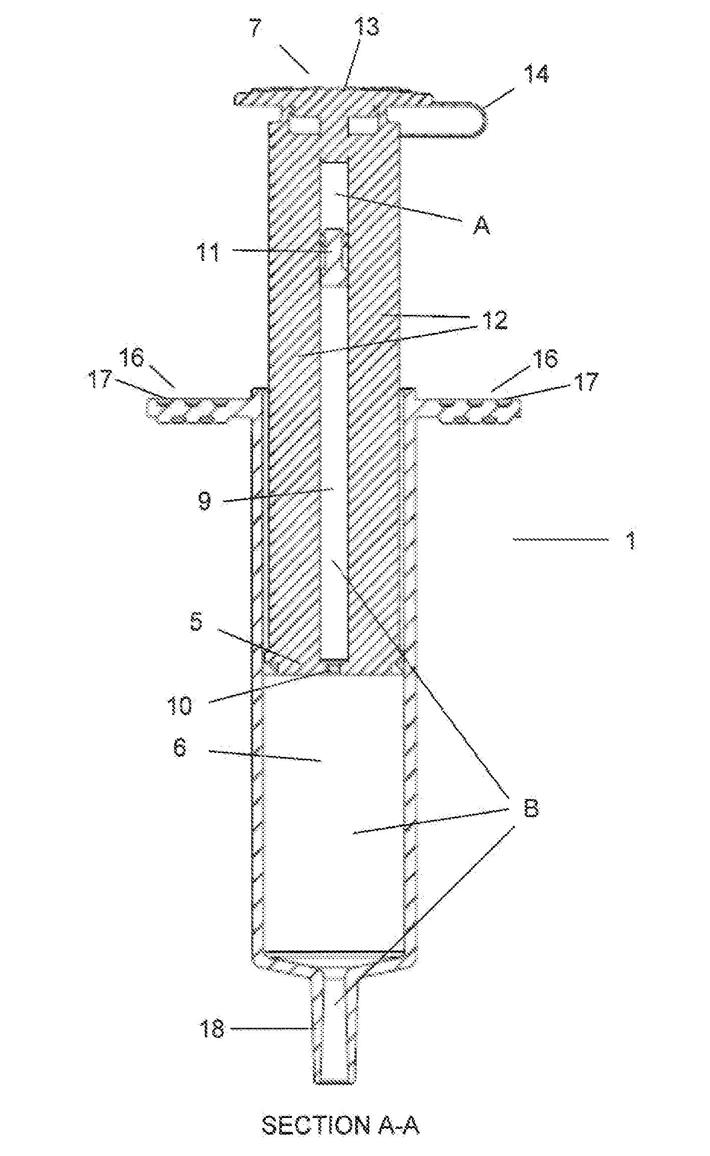
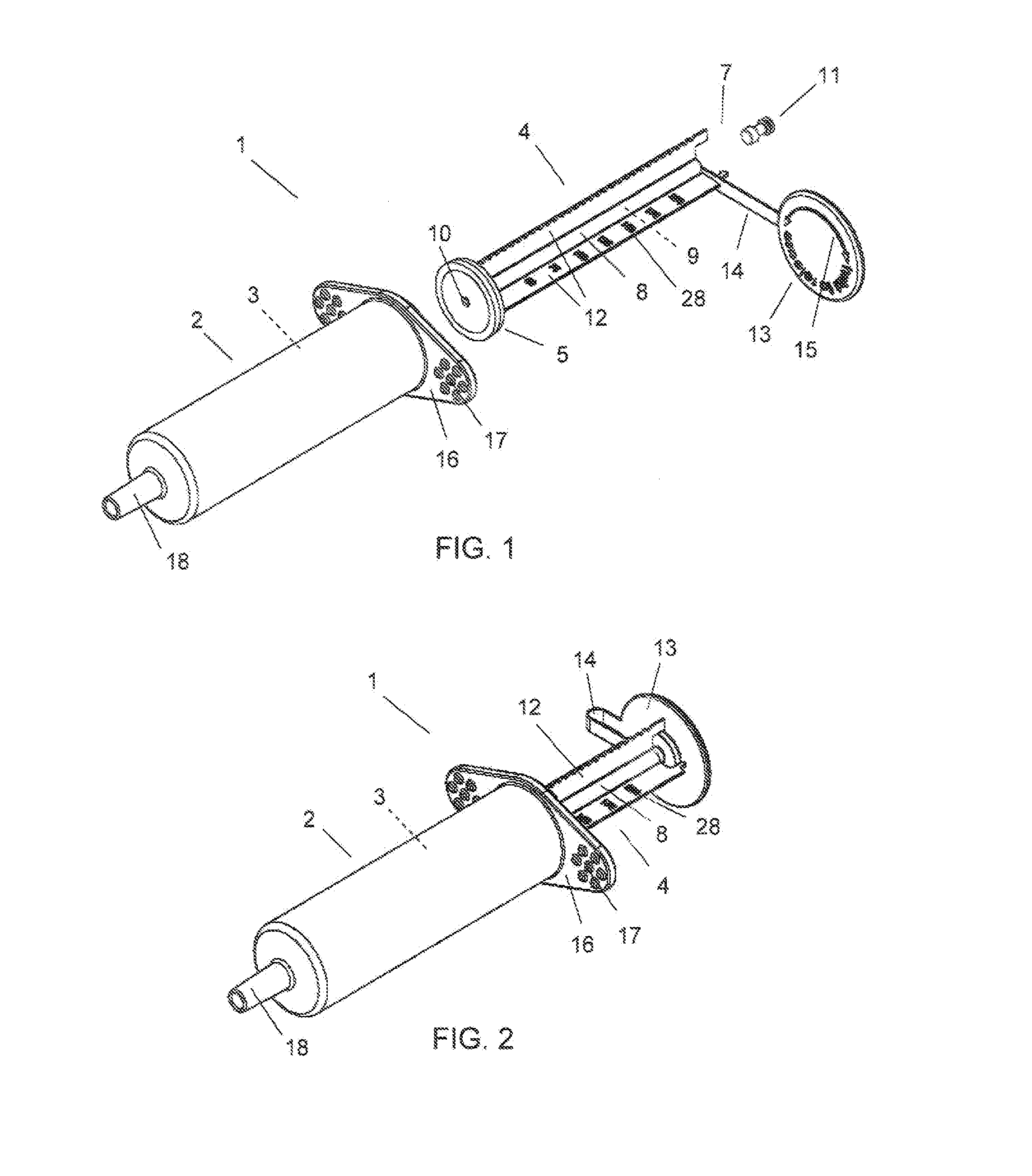
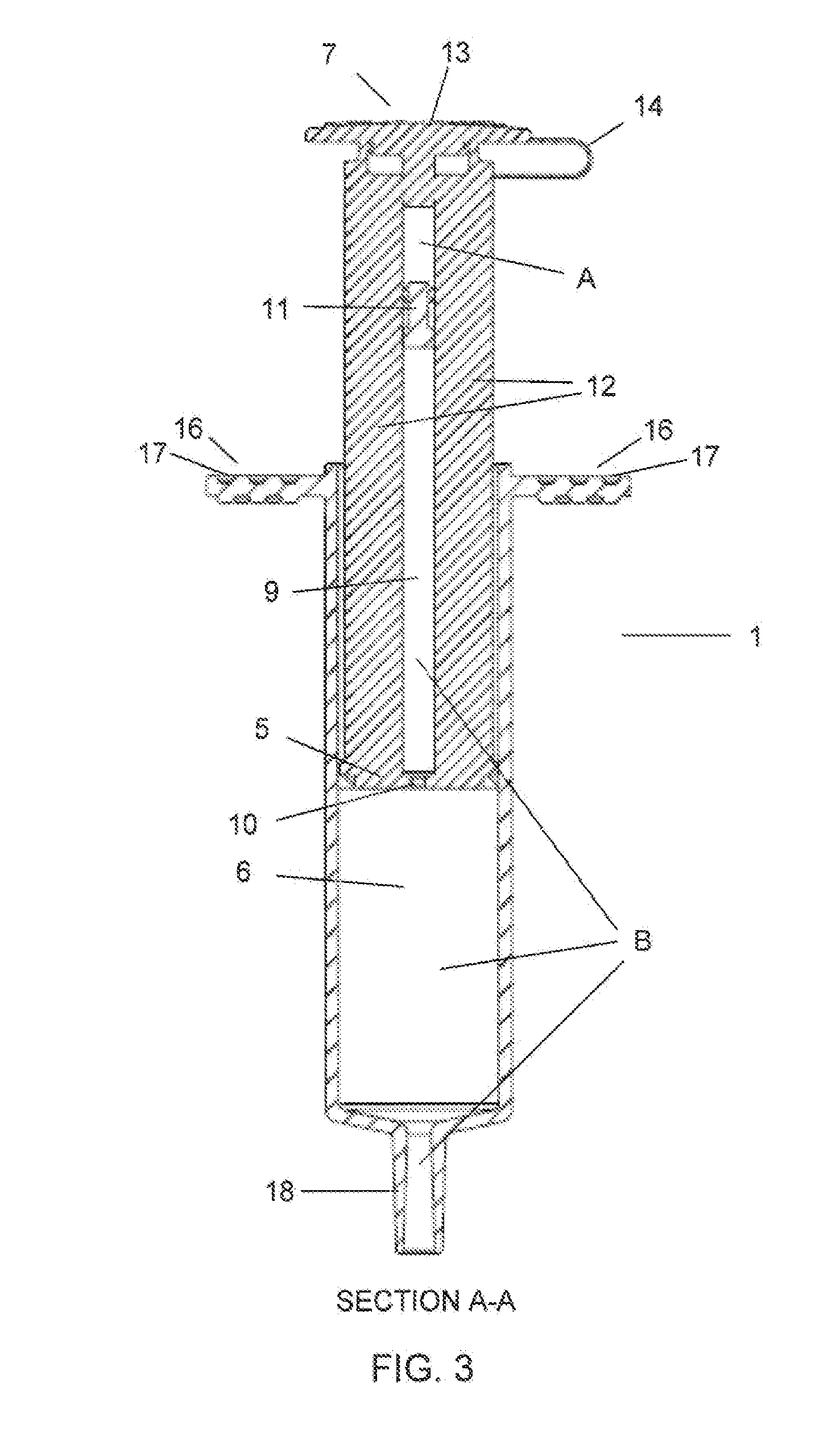
[0032]In FIG. 1 an injection pressurizer 1 according to the invention for pressurizing e.g. an inflatable device to achieve haemostasis is shown. The pressuizer 1 may for example be applied in connection with a femoral compression device as disclosed in WO 2009 / 000665 to inflate the therein described inflatable air cushion, or in connection with a radial compression device as disclosed in WO 96 / 25110, with the difference that the compression element in WO 96 / 25110 then is provided with an inflatable device.

[0033]The pressurizer 1 in FIG. 1 comprises a housing 2 enclosing a first cavity 3, and a plunger 4 adapted to fit inside the housing 2, which is provided with a plunger sealing unit 5 adapted to define a second cavity 6 (FIG. 3) inside the housing 2. The plunger 4 is further provided with an end part 7 at the end opposite the plunger sealing unit 5. The plunger 4 also comprises an elongated tube 8 defining a tube cavity 9 extending from the plunger sealing unit 5 to the end part ...


PUM


Abstract

The invention relates to an injection pressurizer for pressurizing an inflatable device comprising:—a housing enclosing a first cavity;—a plunger adapted to fit inside said housing and provided with a plunger sealing unit adapted to define a second cavity inside said housing, the plunger is further provided with an end part at the end opposite the plunger sealing unit; wherein the plunger further comprises
  • an elongated tube defining a tube cavity extending from said plunger sealing unit to said end part of the plunger, said tube cavity being in fluid communication with said second cavity via an opening in said plunger sealing unit; and a pressure indicating piston adapted to be moveably arranged inside said tube cavity, such that the piston delimits a first volume (A) in said tube cavity from a second volume (B), such that when a pressure is built up in the second volume (B), the piston is moved by the pressure to equalize the pressures of said first volume (A) and said second volume (B), and thereby indicates the pressure in the second volume (B). The invention relates according to another aspect to a method of pressurizing an inflatable device with an injection pressurizer.

Description

FIELD OF THE INVENTION[0001]The present invention relates to an injection pressurizer for pressurizing an inflatable device and a method in connection thereto. In particular, the invention relates to an injection pressurizer for pressurizing an inflatable device adapted to be used against a puncture site in a vessel of a patient to achieve haemostasis.BACKGROUND OF THE INVENTION[0002]To access a patient's vascular system for an invasive medical procedure such as catheterization or similar procedures, a puncture is made in e.g. the femoral artery or the radial artery. Following the medical procedure the flow of blood through the puncture site has to be stopped, so that haemostasis may begin as soon as possible. This may be done by using a compression device.[0003]One example of such a compression device is known from EP 1382306, disclosing a haemostatic device with an inflatable balloon. A main balloon is pressed against a puncture site of a patient and filled with a first fluid to i...

Claims


Application Information

Patent Timeline
IPC IPC(8): A61B17/135
CPCA61B17/0057A61B17/135A61B2017/00557A61B2019/464A61M5/31515A61M5/482A61M5/484A61M5/486A61M5/3137A61M5/48A61B2090/064A61B17/1325
Inventor HANSSON, ERIK
Owner ST JUDE MEDICAL COORDINATION CENT
Why Eureka
Try Eureka