
Propulsion control apparatus

a technology of propulsion control and control apparatus, which is applied in the direction of propulsion by batteries/cells, process and machine control, instruments, etc., can solve the problems of self ventilation type, inability to control the flow of air, so as to reduce the loss of the main circuit element of the auxiliary power supply

Active Publication Date: 2012-11-22
NEXGEN CONTROL SYST LLC
View PDF1 Cites 7 Cited by
  • Summary
  • Abstract
  • Description
  • Claims
  • Application Information

AI Technical Summary

Benefits of technology

[0011]According to the present invention, a propulsion control apparatus can be provided in which, in the case of the configuration in which the auxiliary power supply is connected to the intermediate link connection of the main conversion unit, the loss generated in the main circuit element of the auxiliary power supply is reduced.

Problems solved by technology

Because the strength of the running-vehicle wind depends on the vehicle speed, the cooling ability when a self ventilation type is adopted decreases with slowing of the vehicle speed, and becomes the lowest during stopping of the vehicle, while the running-vehicle wind cannot be expected.
Because the voltage generally depends on a main motor (motor for driving the vehicle) as a load on the main conversion unit, the voltage is set at a higher level, and thereby loss generated in the main circuit element tends to become larger than that in a configuration in which electric power is directly obtained from a main transformer.

Method used


Image

  • Propulsion control apparatus
  • Propulsion control apparatus
  • Propulsion control apparatus

Examples


embodiment 1

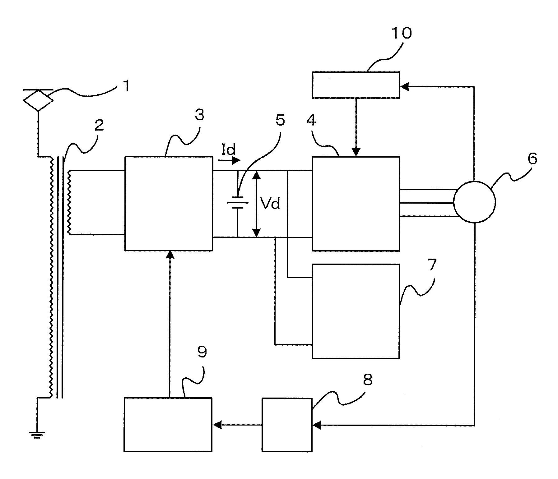
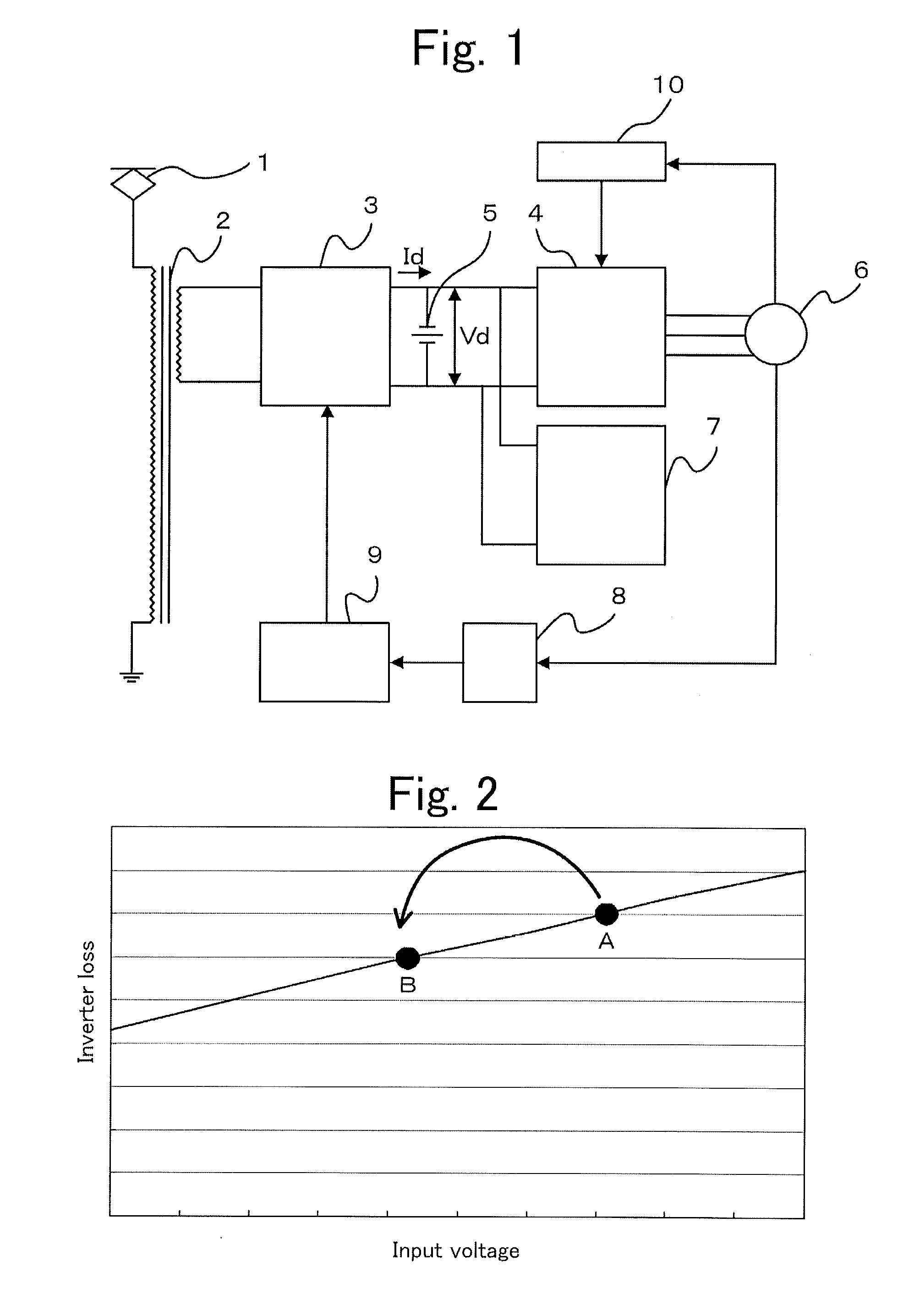
[0020]FIG. 1 is a diagram illustrating a configuration example of an electric power conversion system according to Embodiment 1 of the present invention. In FIG. 1, the electric power conversion system is mounted in an AC electric motor vehicle, and AC current transmitted from a power station through a power line is inputted from a pantograph 1. A main transformer 2 converts voltage outputted from the pantograph 1 to output.

[0021]A converter 3 converts the output of the main transformer 2 from AC to DC. The voltage outputted from the converter 3 is an intermediate link voltage. An inverter 4 converts the output of the converter 3 from DC to three-phase AC. A filter capacitor 5 is provided on the DC output side of the converter 3, which removes output noises of the converter 3 and smoothes the intermediate link voltage. The three-phase AC is inputted from the inverter 4 into a main motor 6 to drive the electric motor vehicle. An auxiliary power supply 7 is connected to an intermediat...


PUM


Abstract

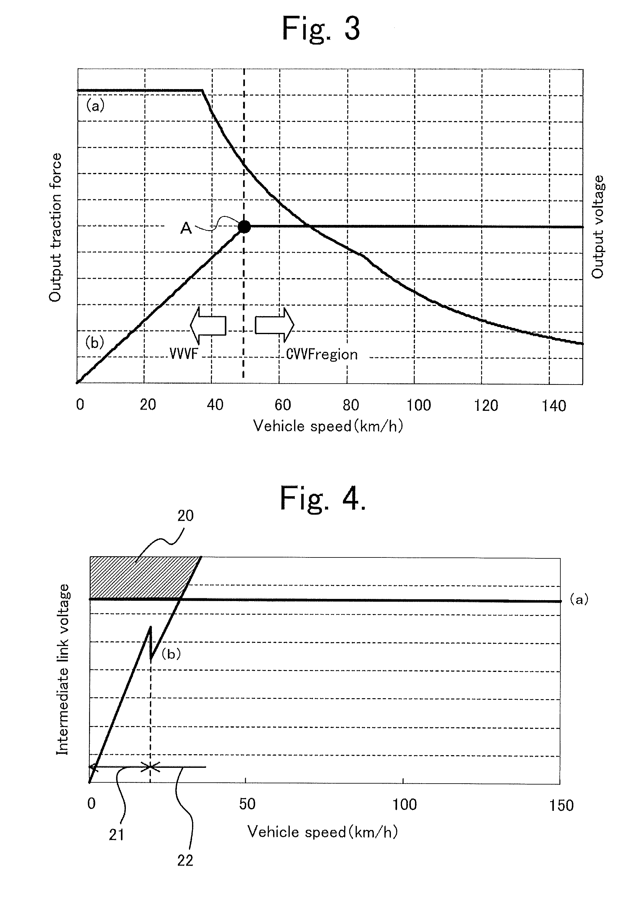
In a configuration in which an auxiliary power supply is connected to an intermediate link circuit of a main conversion unit, intermediate link voltage as input voltage of the auxiliary power supply is set at higher voltage depending on the main conversion unit as a main unit, and loss generated in a main circuit element of the auxiliary power supply increases; therefore, a problem has occurred that a cooling unit has to be increased in size. The main conversion unit recognizes a low-speed and stop state by monitoring a vehicle speed, and varies the intermediate link voltage corresponding to the vehicle speed; thereby, the loss generated in the main circuit element of the auxiliary power supply is reduced at the low-speed and stop state where cooling ability is decreased; as a result, small sizing and light weighting of the cooling unit is achieved.

Description

TECHNICAL FIELD[0001]The present invention relates to a propulsion control apparatus for an AC electric motor vehicle.BACKGROUND ART[0002]Electric motor vehicles are generally provided with an auxiliary power supply for supplying electric power to, for example, lighting and air conditioning systems therein. The loads (for example, the lighting and air conditioning systems) on the auxiliary power supply generate heat (loss), regardless of vehicle speed, in a main circuit element of the auxiliary power supply. Accordingly, cooling of the main circuit element is necessary. With respect to the cooling system for the main circuit element of the auxiliary power supply, a self ventilation type using ram wind induced by a running vehicle (running-vehicle wind) and a forced wind cooling type using a fan are applicable.[0003]Because the strength of the running-vehicle wind depends on the vehicle speed, the cooling ability when a self ventilation type is adopted decreases with slowing of the v...

Claims


Application Information

Patent Timeline
Patent Type & Authority Applications(United States)
IPC IPC(8): B60L15/20
CPCH02P23/009H02P27/06Y02T10/7258B60L2200/26B60L9/28Y02T10/70Y02T10/92Y02T10/7072Y02T90/14B60L53/20B60L50/52B60L15/20B60L2240/12B60L2210/30B60Y2200/91Y02T10/72
Inventor MATSUMOTO, TAKEO
Owner NEXGEN CONTROL SYST LLC
Learn More