
Power Supply Apparatus, Light Emitting Apparatus, and Display Apparatus

a technology of light-emitting apparatus and power supply apparatus, which is applied in the direction of electric variable regulation, process and machine control, instruments, etc., can solve the problems of power supply switching curtailment or halting, and achieve the effect of driving the load circuit more stably and more stably

Inactive Publication Date: 2008-05-01
ROHM CO LTD
View PDF2 Cites 30 Cited by
  • Summary
  • Abstract
  • Description
  • Claims
  • Application Information

AI Technical Summary

Benefits of technology

The present invention provides a power supply apparatus that can efficiently drive multiple load circuits. The apparatus includes a switching power supply and a drive controller that controls the driving states of the load circuits. The drive controller drives the load circuits in a time division manner, and the switching power supply halts its operation during a non-drive period in which none of the load circuits are driven. This results in reduced power consumption and high efficiency. The load circuits can be light emitting elements, and the apparatus can be used in a display apparatus or a light emitting apparatus. The invention also includes a method for starting the switching operation of the switching power supply to stabilize the output voltage. The technical effects of the invention are reduced power consumption, improved efficiency, and improved stability of the load circuits.

Problems solved by technology

When halting the switching operation, the switching power supply may curtail or halt power supply to an internal circuit thereof.

Method used


Image

  • Power Supply Apparatus, Light Emitting Apparatus, and Display Apparatus
  • Power Supply Apparatus, Light Emitting Apparatus, and Display Apparatus
  • Power Supply Apparatus, Light Emitting Apparatus, and Display Apparatus

Examples


first embodiment

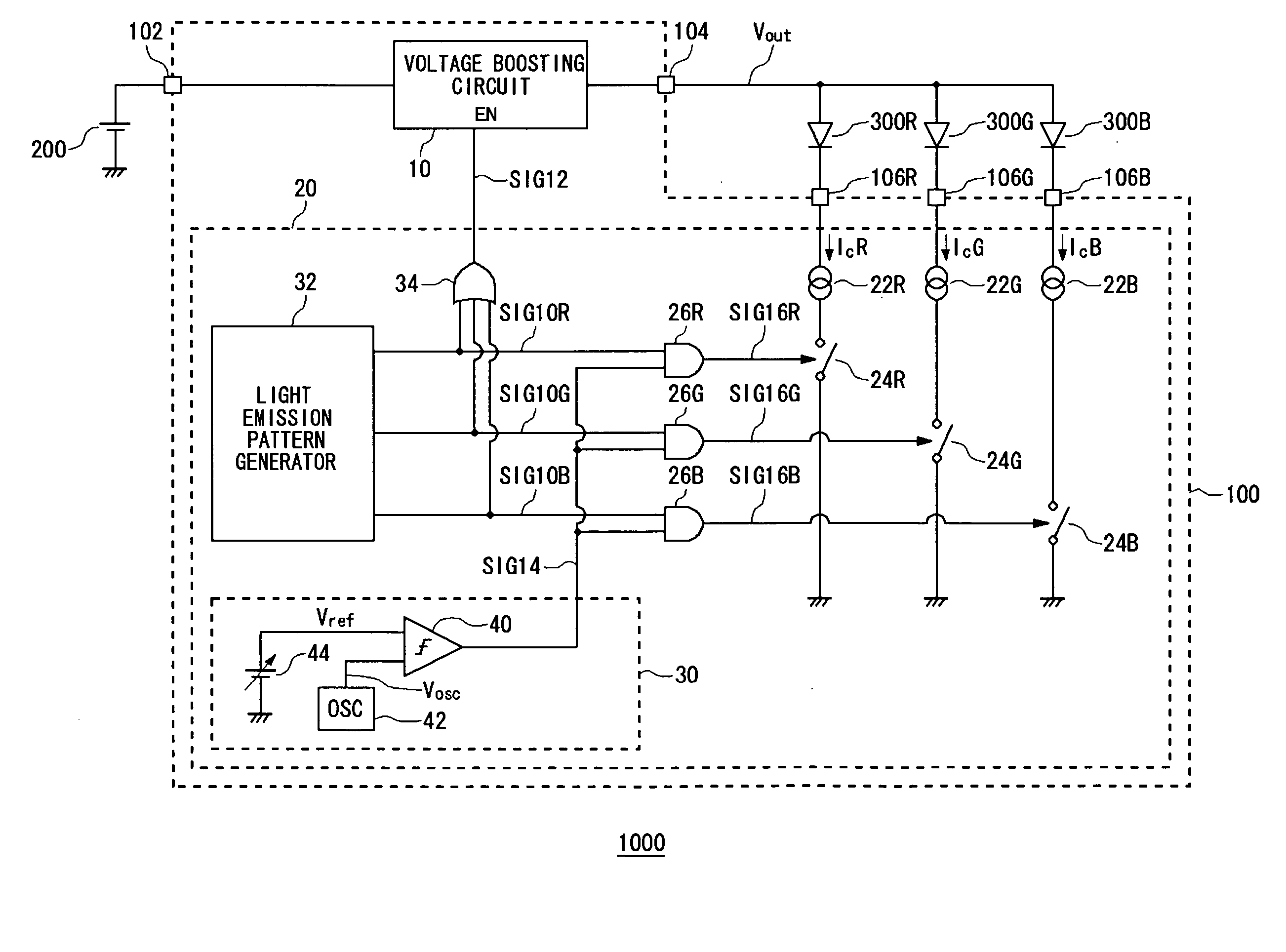
[0034] First, an explanation is given of an outline of a power supply apparatus according to a first embodiment of the present invention. The power supply apparatus is an LED drive circuit for driving LEDs corresponding to three colors RGB, used as a backlight of a liquid crystal panel. The LED drive circuit boosts battery voltage outputted from a battery to voltage necessary to drive the LEDs, and also controls current flowing in each LED to make the LEDs emit light at a desired luminance. The LED drive circuit performs time division on each LED by a field sequential system, to emit light.

[0035] Below, an explanation is given concerning a configuration of the power supply apparatus according to the present embodiment.

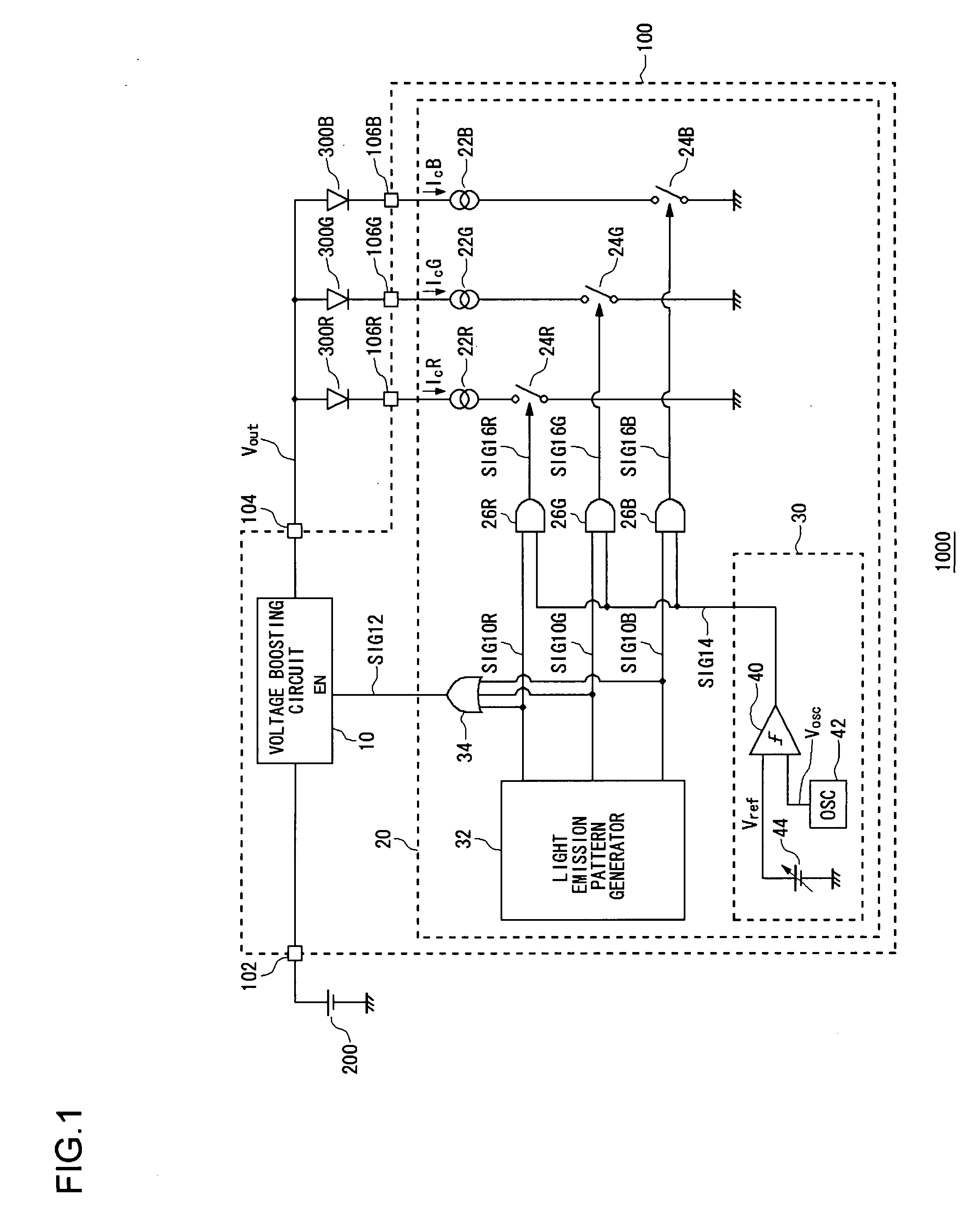
[0036]FIG. 1 is a circuit diagram showing a configuration of a light emitting apparatus 1000 according to a first embodiment. The light emitting apparatus 1000 includes light emitting diodes 300R to 300B that are light emitting elements, and a power supply apparatus ...

second embodiment

[0064] A light emitting apparatus according to a second embodiment, similar to the first embodiment, also includes light emitting diodes 300 used as a background light of a liquid crystal panel. The light emitting apparatus according to the present embodiment causes the light emitting diodes 300R to 300B to emit light more stably at a desired luminance.

[0065]FIG. 4 is a circuit diagram showing a configuration of the light emitting apparatus 2000 according to the present embodiment. In FIG. 4, component elements that are the same as or equivalent to those in FIG. 1 are given the same reference symbols, and explanations are omitted as appropriate. The light emitting apparatus 2000 includes the light emitting diodes 300R to 300B and a power supply apparatus 400.

[0066] The power supply apparatus 400 is further provided with delay circuits 60R to 60B, added to the power supply apparatus 100 of FIG. 1. The delay circuits 60R to 60B respectively delay the light emission control signals S...


PUM


Abstract

In the power supply apparatus, a voltage booster circuit supplies a drive voltage (Vout) to a plurality of light emitting diodes. A drive controller controls a driving state, that is, light emission intensity, of each of the plurality of light emitting diodes. The drive controller drives the plurality of load circuits in a time division manner, the voltage booster circuit is provided with an enabling terminal, and a switching operation is halted during a non-light-emission period in which none of the light emitting diodes is driven by the drive controller. A light emission pattern generator generates light emission control signals which direct light emission of each of the light emitting diodes. The voltage booster circuit halts a switching operation in a non-light-emission period in which none of the light emitting diodes emits light, by a logical operation on the light emission control signals.

Description

BACKGROUND OF THE INVENTION [0001] 1. Field of the Invention [0002] The present invention relates in particular to a power supply apparatus that uses a switching power supply. [0003] 2. Description of the Related Art [0004] In recent years, among small sized information terminals such as mobile telephones, PDAs (Personal Digital Assistants) and the like, devices are used that include those in which a voltage is required that is higher than an output voltage of a battery, as in, for example, a Light Emitting Diode (referred to as LED below) used as a backlight for liquid crystal panels, and the like. In many of these small sized information terminals, Li-ion batteries are used; the output voltage thereof is normally about 3.5 V, and, when fully charged, about 4.2 V, but the LED requires, as a drive voltage thereof, a voltage higher than the battery voltage. In this way, in cases in which a voltage higher than the battery voltage is required, the battery voltage is boosted using a vol...

Claims


Application Information

Patent Timeline
Patent Type & Authority Applications(United States)
IPC IPC(8): H02M3/137H02M3/155H02J3/14H05B39/04
CPCG09G3/3413Y02B20/346H05B33/0827H05B33/0818H05B45/38H05B45/46Y02B20/30
Inventor MIGUCHI, MITSUAKI
Owner ROHM CO LTD
Learn More