

Gas detection apparatus and gas detection method
- Summary
- Abstract
- Description
- Claims
- Application Information
AI Technical Summary
Benefits of technology
Problems solved by technology
Method used
Image

Examples
embodiment
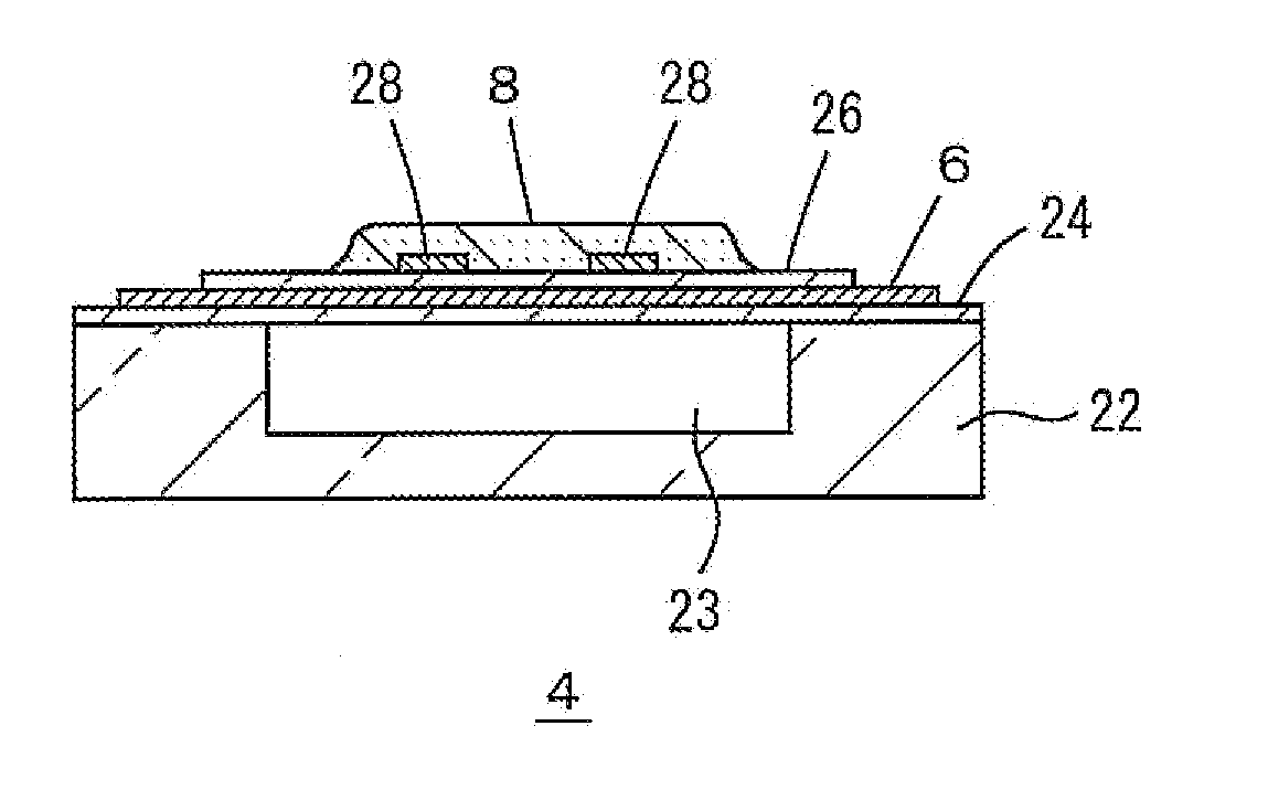
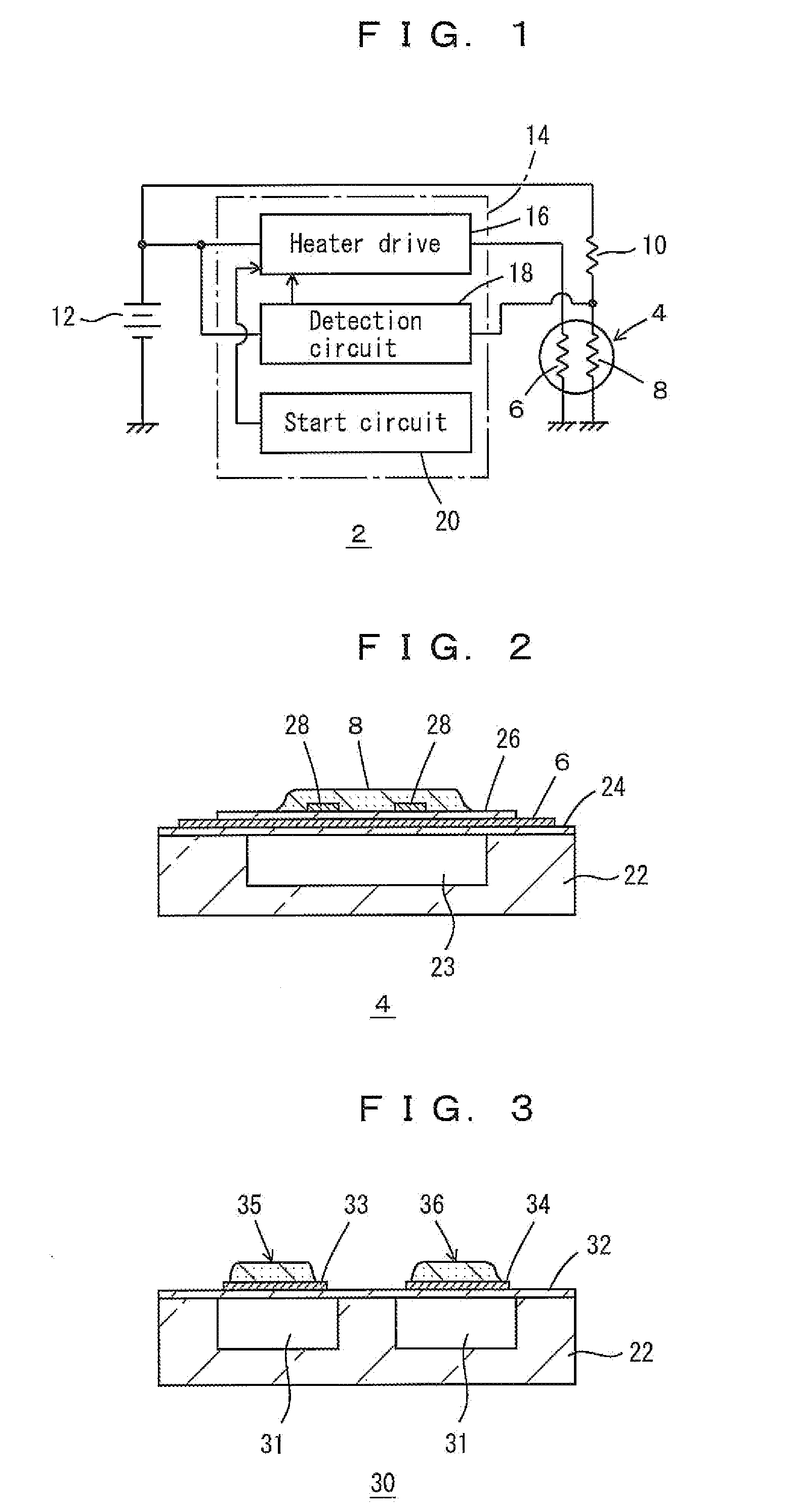
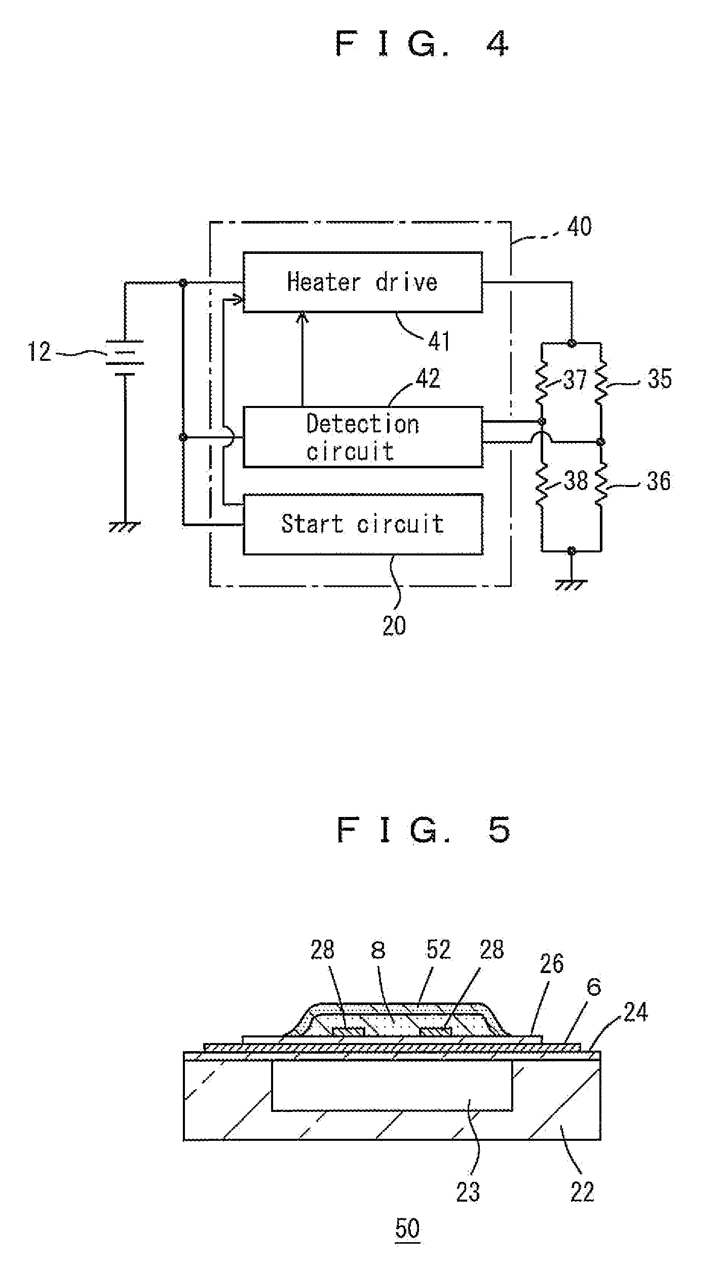
[0026]FIGS. 1 to 7 show a gas detection apparatus 2 and its modified examples according to the embodiment. In the drawings, 4 denotes a SnO2 MEMS gas sensor (hereinafter, a gas sensor 4) that is provided with a heater 6 and a SnO2 film 8. 10 denotes a load resistor, 12 denotes a battery that functions as a power source, and 14 denotes a microcomputer as a drive circuit for the gas sensor 4, the microcomputer functioning as a heater drive 16, a detection circuit 18, and a start circuit 20. The heater drive 16 controls the electrical power to the heater 6 through PWM (pulse width modulation) or the like, and, for example, drives the heater 6 in 30-second cycles in order from a low level (0.4 seconds), to a high level (0.1 seconds), and then to a 0 level. The detection circuit 18 detects methane as detection target gas based on the resistance of the SnO2 film 8 or an amount corresponding thereto, which in this embodiment is the voltage applied to the SnO2 film 8, when the heater electr...
PUM
 Abstract
Description
Claims
Application Information