Electrolyte supply tanks and bubbler tanks having improved gas diffusion properties for use in electrolyzer units

Inactive Publication Date: 2012-11-29
RICHARDSON DAVID THOMAS
View PDF1 Cites 15 Cited by
  • Summary
  • Abstract
  • Description
  • Claims
  • Application Information

AI Technical Summary

Benefits of technology

[0014]The present invention improves on existing technology for preventing mist containing electrolyte in solution or particle form from being introduced into the induction system of an internal combustion engine equipped with an oxyhydrogen gas generation system. The present invention utilizes gas diffusers made of porous polyethylene. A first diffuser having a pore diameter of about 70 μm is used at the bottom of the electrolyte supply tank. Oxyhydrogen gas generated by the electrolyzer is ducted into the electrolyte supply tank via the 70 μm-pore diffuser. A pore diameter of 70 μm is deemed optimum for this application because the incoming oxyhydrogen gas is typically laden with electrolyte mist and droplets. If the pore diameter is significantly smaller than 70 μm, the electrolyte mist and droplets must be forced through the pores, which severely restricts gas flow through the diffuser. A bubbler is also used in combination with a second polyethylene gas diffuser having a pore diameter of about 35 μm. The bubbler is down stream of the electrolyte supply tank. After the oxyhydrogen gas leaves the electrolyte supply tank, it is relati

Problems solved by technology

If the pore diameter is significantly smaller than 70 μm, the electrolyte mist and droplet

Method used


Image

  • Electrolyte supply tanks and bubbler tanks having improved gas diffusion properties for use in electrolyzer units
  • Electrolyte supply tanks and bubbler tanks having improved gas diffusion properties for use in electrolyzer units
  • Electrolyte supply tanks and bubbler tanks having improved gas diffusion properties for use in electrolyzer units

Examples


Embodiment Construction

[0021]The invention will now be described in detail with reference to the attached drawing figures. It should be understood that although no attempt has been made to inaccurately portray the drawings, they still may not be drawn to scale.

[0022]The present invention is designed to eliminate virtually all electrolyte from the oxyhydrogen gas that is provided to the induction system of an internal combustion engine. The term “internal combustion engine”, as used herein, refers to any engine in which a fuel-air mixture is burned within the engine itself so that the hot gaseous products of combustion act directly on the surfaces of engine's moving parts. Such moving parts include, but are not limited to, pistons or turbine rotor blades. Internal-combustion engines include spark-ignition and compression-ignition engines of both two-stroke and four-stroke cycle types, gas turbine engines, jet engines, and rocket engines.

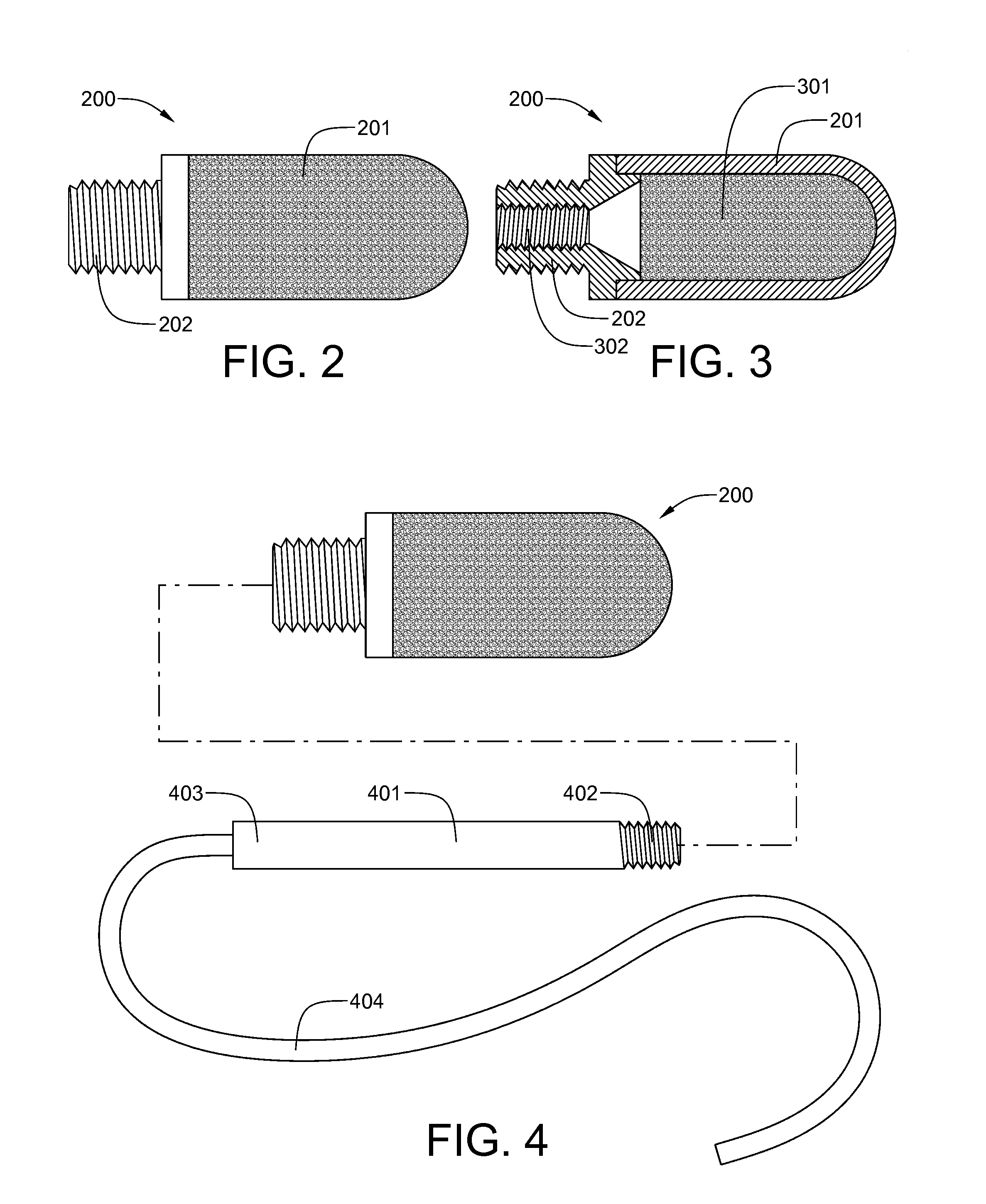
[0023]Referring now to FIG. 2, a porous polyethylene air diffuser 200 ...


PUM


Abstract

Electrolyte supply tanks and bubbler tanks for oxyhydrogen gas generation systems are provided which eliminate the introduction of electrolyte and water into the induction systems of internal combustion engines. Both types of tanks are equipped with porous polyethylene gas diffusers which break up incoming gas into microscopic bubbles, thereby facilitating the absorption of electrolyte mist and droplets returning to the electrolyte supply tank and minimizing splashing of incoming gas in bubbler tanks. Air diffusers having an average pore diameter of about 70 μm are installed near the bottom of the electrolyte supply tanks, while air diffusers having an average pore diameter of about 35 μm are installed near the bottom of the bubbler tanks.

Description

[0001]This application has a priority date based on the filing of Provisional Patent Application No. 61 / 490,582, titled Electrolyte Supply Tanks and Bubbler Tanks Having Improved Gas Diffusion Properties for Use in Electrolyzer Units, by the same inventor, on May 26, 2012.BACKGROUND OF THE INVENTION[0002]1. Field of the Invention[0003]The present invention is related to an apparatus and method of improving the fuel efficiency of an internal combustion engine, and in particular, to an apparatus and method for hydrolyzing water into a mixture comprising hydrogen gas and oxygen gas, which is combined with the fuel and air mixture used in an internal combustion engine.[0004]2. History of the Prior Art[0005]During the past 30 years, significant advances have been made in internal combustion engine technology that have dramatically improved the efficiency of internal combustion engines. For gasoline engines, four-valve-per-cylinder combustion chamber designs, coupled with computer monitor...

Claims


Application Information

Patent Timeline
IPC IPC(8): C25B15/08C25B1/00
CPCC25B15/08Y02E60/366F02M25/12C25B1/08Y02E60/36C25B1/04C25B9/73
Inventor RICHARDSON, DAVID THOMAS
Owner RICHARDSON DAVID THOMAS
Why Eureka
Try Eureka