Rotor for rotating electric machine

a technology of rotating electric machines and rotors, which is applied in the direction of dynamo-electric machines, magnetic circuit rotating parts, magnetic circuit shapes/forms/construction, etc., can solve the problems of reducing the rotation efficiency of the rotor, reducing the rotation efficiency of the motor, and contributing to an increase in the manufacturing and material costs of the rotor

Active Publication Date: 2012-11-29
AISIN AW CO LTD
View PDF6 Cites 65 Cited by
  • Summary
  • Abstract
  • Description
  • Claims
  • Application Information

AI Technical Summary

Benefits of technology

[0034]According to the thirteenth aspect, the center portion of the rotor core most susceptible to heat buildup can be intensively cooled. Further, coolant supplied from the supply opening portion to the cooling medium flow space moves along the cooling inner circumferential face toward the cooling medium discharge hole on both end sides in the rotor axial direction, whereby the inner circumferential face of the rotor core can be suitably cooled over a whole axial area. Thus, the permanent magnet provided in the rotor core can be suitably cooled.

Problems solved by technology

This makes the rotor susceptible to the rotary reaction force from the cooling medium, and causes a reduction in the rotation efficiency of the rotor.
In such case, the rotation loss produced by the rotation of the rotor increases and causes a reduction in the rotation efficiency of the motor.
However, adopting such a structure would contribute to an increase in the manufacturing and material costs of the rotor.

Method used


Image

  • Rotor for rotating electric machine
  • Rotor for rotating electric machine
  • Rotor for rotating electric machine

Examples


first embodiment

1. First Embodiment

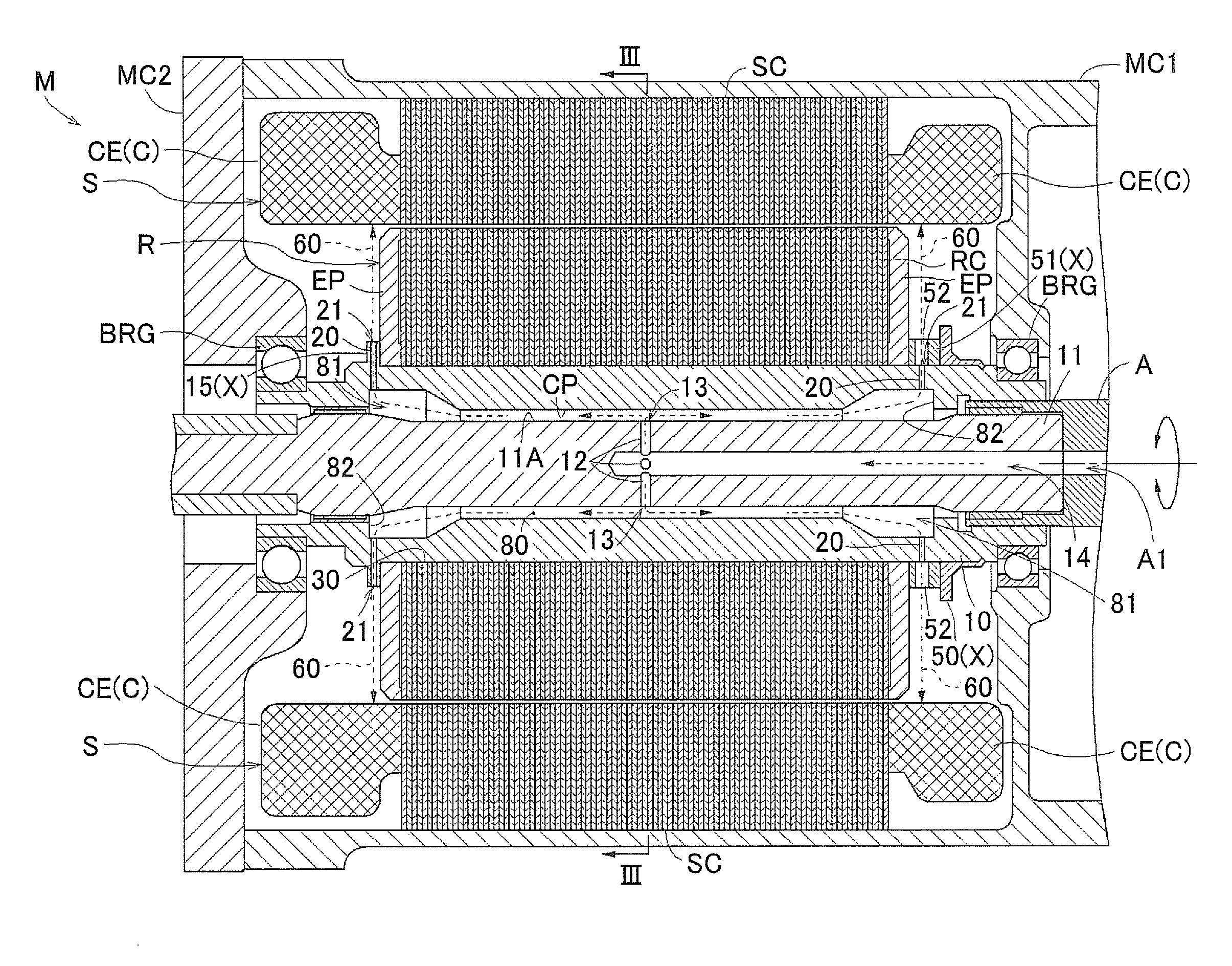
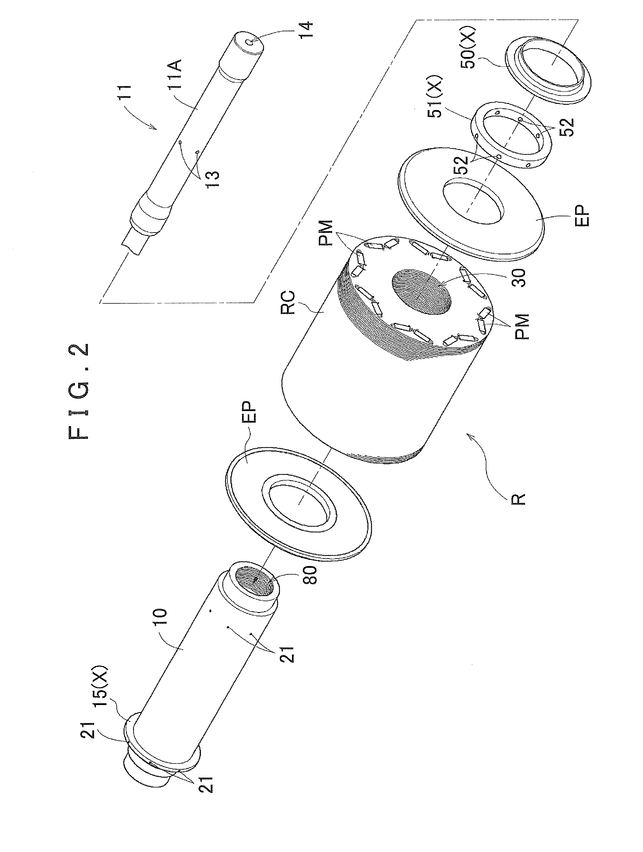
[0056]Hereinafter, a rotor R for a rotating electric machine (referred to as a “rotor R” below) according to the present invention will be described. As described in detail later, the present rotor R is configured to enable a coolant (that corresponds to a “cooling medium” of the present invention) to cool a permanent magnet PM provided in the rotor R, while reducing the rotary reaction force that the coolant applies to the rotor R. It should be noted that, although a common cooling oil is preferably used as the coolant, the coolant is not limited to this.

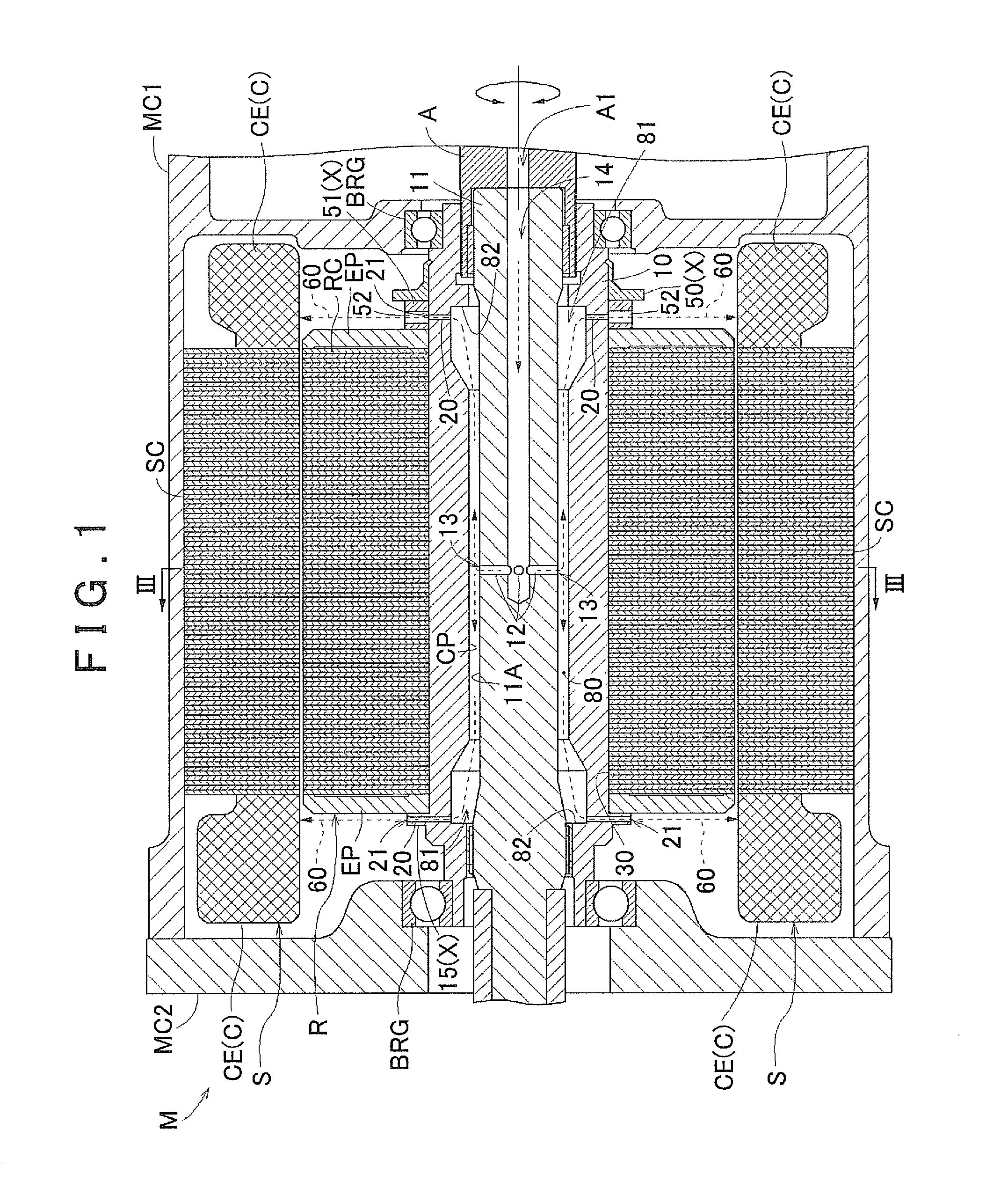
[0057]FIG. 1 is a side cross-sectional view of a rotating electric machine M that is provided with the rotor R according to the present embodiment. As shown in FIG. 1, the rotating electric machine M is constituted such that a stator S and the rotor R are accommodated inside a space that is formed by a case body MC1 and a cover MC2 that covers an opening portion of the case body MC1. The stator S is fixed to the ...

second embodiment

2. Second Embodiment

[0084]Next, a second embodiment of the rotor R according to the present invention will be described. The rotor R of the second embodiment differs from the rotor R of the first embodiment described above in that the annular member 51 formed with the radial discharge hole 52 is not provided, and the discharge opening portion 21 is not formed on the flange portion 15. Otherwise, the rotor R of the second embodiment is identical to the rotor R of the first embodiment. The following description will thus focus on points where the rotor R of the second embodiment differs from the rotor R of the first embodiment.

[0085]FIG. 4 shows a side cross-sectional view of the rotating electric machine M that is provided with the rotor R according to the present embodiment. FIG. 5 shows a cross section taken along a line V-V in FIG. 4, and FIG. 6 shows a cross section taken along a line VI-VI in FIG. 4. FIG. 7 shows an exploded perspective view of the rotor R. As shown in FIGS. 4 t...

third embodiment

3. Third Embodiment

[0095]Next, a third embodiment of the rotor R according to the present invention will be described. The rotor R of the third embodiment differs from the rotor R of the first embodiment described above in that the cooling medium discharge hole 20 includes an axial groove 91. Otherwise, the rotor R of the third embodiment is identical to the rotor R of the first embodiment. The following description will thus focus on points where the rotor R of the third embodiment differs from the rotor R of the first embodiment.

[0096]FIG. 8 shows a partial side cross-sectional view of the rotating electric machine M that is provided with the rotor R according to the present embodiment. FIG. 9 shows a partial perspective view of the rotor shaft 10. As shown in FIGS. 8 and 9, the rotor shaft 10 provided with the rotor R of the third embodiment includes the axial groove 91.

[0097]Here, similar to the second embodiment described above, the shaft-end fixing member 50 is provided in con...


PUM


Abstract

In a rotor for the dynamo, the interior circumference face of a rotor core main body makes contact in a thermally transmissible manner with a rotor axle, and the rotor axle includes a cooling medium circulation space. The rotor is provided with a cooling medium supply member, which supplies the cooling medium to the cooling medium circulation space. The cooling medium supply member is provided with a cooling medium supply path that extends in the rotor axle direction, and cooling medium supply holes that extend externally in the direction of the rotor diameter. The cooling medium supply holes are provided with supply apertures that open toward the cooling interior circumference face. The rotor axle is provided with cooling medium discharge holes that extend externally in the direction of the rotor diameter. The cooling medium discharge holes are provided with discharge apertures that open externally in the diameter direction.

Description

INCORPORATION BY REFERENCE[0001]The disclosure of Japanese Patent Application No. 2010-068756 filed on Mar. 24, 2010 including the specification, drawings and abstract is incorporated herein by reference in its entirety.BACKGROUND OF THE INVENTION[0002]The present invention relates to a rotor for a rotating electric machine that has a cylindrical rotor core and a rotor shaft fixed so as to rotate together with the rotor core.DESCRIPTION OF THE RELATED ART [0003]Rotating electric machines have been used in the past as a source of power for driving various types of equipment. A known rotating electric machine includes a stator having a coil, and a rotor having a permanent magnet. However, equipment driven by a rotating electric machine often requires a large output from the rotating electric machine, which increases the amount of heat generated by various components of the rotating electric machine, especially by the coil and the permanent magnet. Copper loss and iron loss are among t...

Claims


Application Information

Patent Timeline
Patent Type & Authority Applications(United States)
IPC IPC(8): H02K9/00
CPCH02K1/2766H02K9/19H02K1/32H02K1/28
Inventor YAMAMOTO, YOSHIHISANAKAMORI, YUKINORIMURAKAMI, SATOSHIMIYOSHI, YOICHIGI, MEIO
Owner AISIN AW CO LTD
Why Eureka
Try Eureka