Solar charger for charging power battery

a technology for solar cells and power batteries, applied in the field of solar chargers, can solve the problems of limiting the range and area of electric buses, devices and machines that require high power, etc., and achieve the effect of boosting the voltage for charging the power battery

Active Publication Date: 2012-11-29
BYD CO LTD
View PDF113 Cites 17 Cited by
  • Summary
  • Abstract
  • Description
  • Claims
  • Application Information

AI Technical Summary

Benefits of technology

[0008]An embodiment of the present disclosure provides a solar charger for charging a power battery, comprising: a photo-sensitive unit configured to detect light intensity; a charging unit configured to receive a voltage transformed from solar energy and to boost the voltage for charging the power battery; a switch unit coupled between the charging unit and the power battery and configured to disconnect the charging unit from the power battery or connect the charging unit with the power battery; and a

Problems solved by technology

These constraints limit the range and areas that the electric bus can serve.
Solar chargers, however, are conventionally used for low-power devi

Method used


Image

  • Solar charger for charging power battery
  • Solar charger for charging power battery
  • Solar charger for charging power battery

Examples


first embodiment

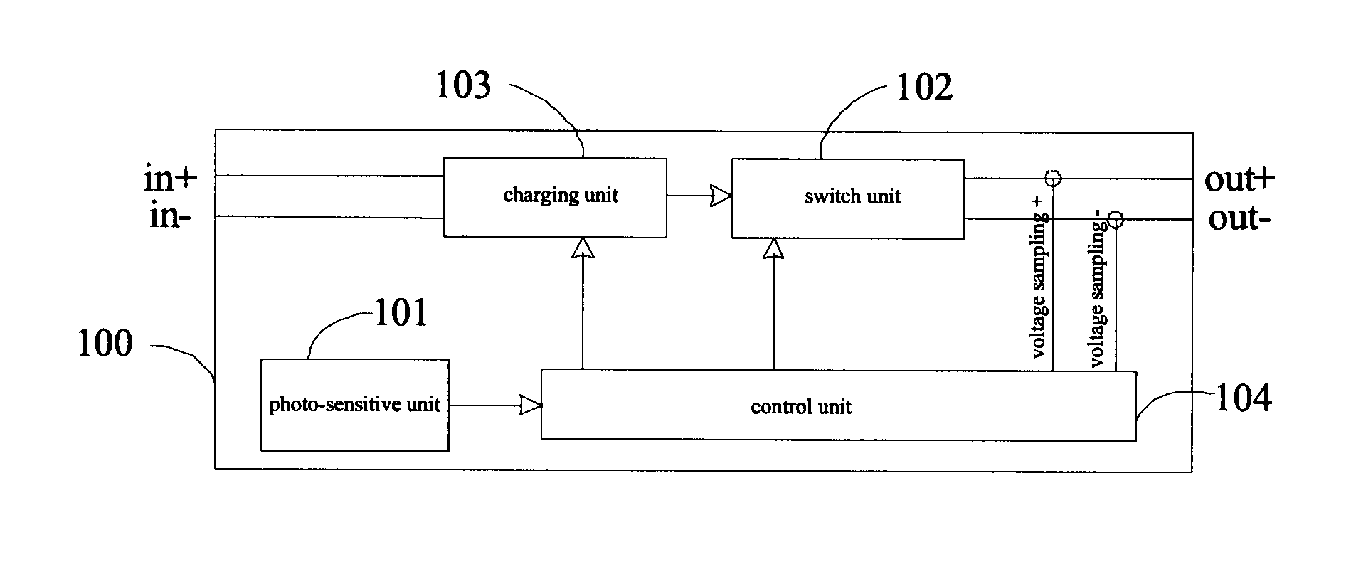
[0019]As shown in a first embodiment in FIG. 1, the solar charger 100 comprises: a photo-sensitive unit 101, a switch unit 102, a charging unit 103, and a control unit 104. The control unit 104 is coupled to each of the photo-sensitive unit 101, the switch unit 102, and the charging unit 103.

[0020]The photo-sensitive unit 101 is configured to detect the light intensity and to send the light intensity to the control unit 104. For example, the photo-sensitive unit 101 may include a photo-sensitive resistor or other photo-sensitive components.

[0021]The switch unit 102 is coupled between the charging unit 103 and the power battery and configured to disconnect the charging unit 103 from the power battery or connect the charging unit 103 with the power battery under the control of the control unit 104. For example, the switch unit 102 may be a relay. When the solar charger 100 satisfies the charging conditions, the control unit 104 may switch on the relay to allow the charging unit 103 to...

second embodiment

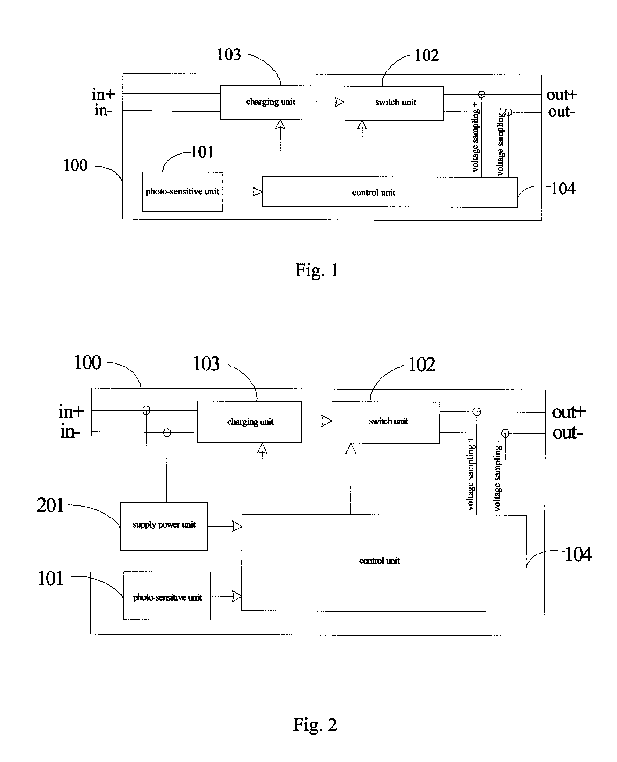
[0026]In a second embodiment shown in FIG. 2, the solar charger 100 further comprises a power battery unit 201 coupled to the control unit 104, and configured to receive and stabilize the voltage that has been transformed from the solar energy and input into the charging unit 103 to power the control unit 104; and when the voltage transformed from the solar energy reaches a second predetermined value, the control unit 104 starts to operate. Thus, when the voltage input into the charging unit 103 is lower than the second predetermined value, the control unit 104 may not operate, which prevents the solar charger 100 from operating. When the voltage input into the charging unit 103 reaches or is higher than the second predetermined value, the solar charger 100 can then start to operate. In some embodiments, the second predetermined value may be no less than 12 V, and an exemplary value may be 80 V. The second predetermined value can have different values depending on the actual operati...

third embodiment

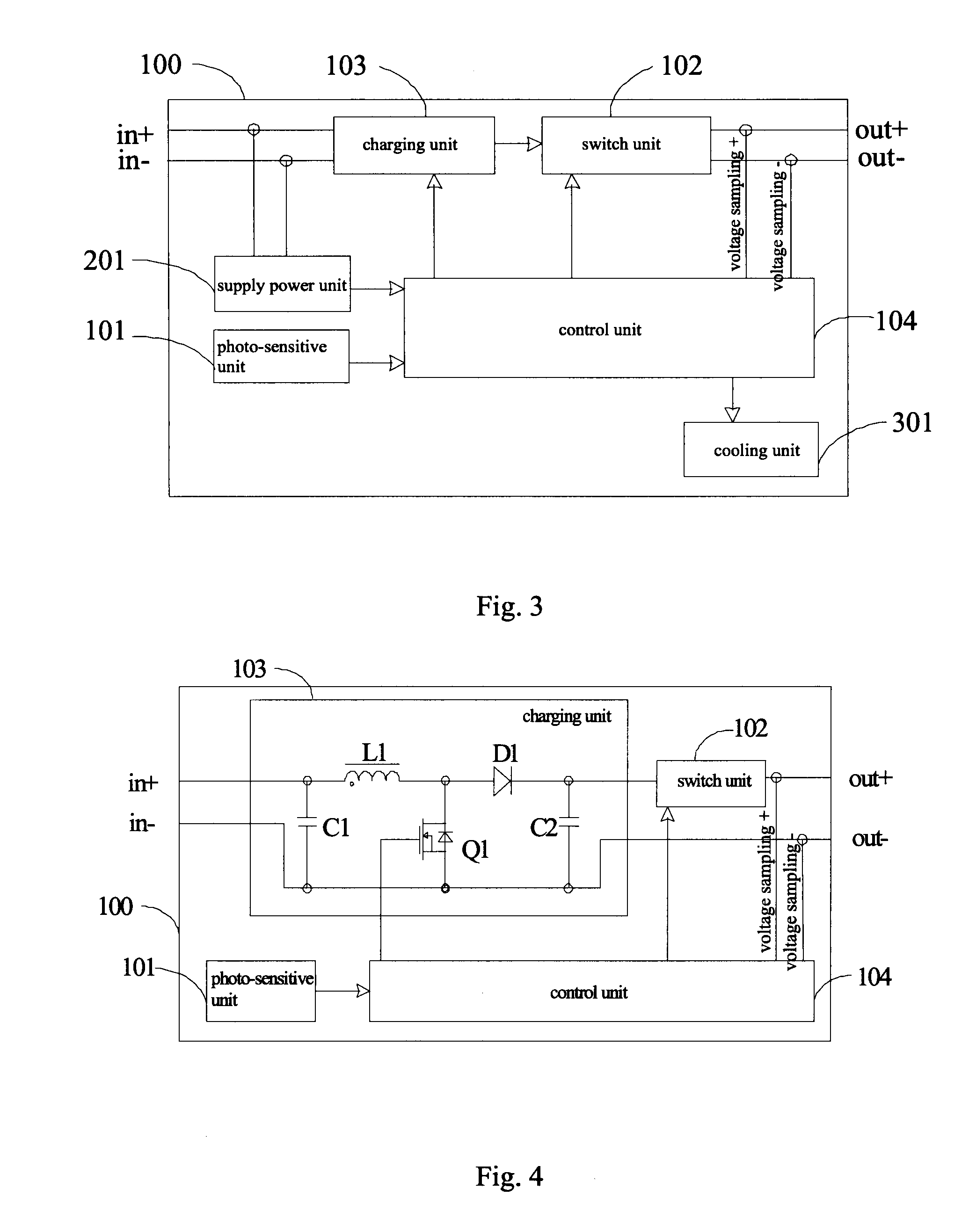
[0030]In the present disclosure, as shown in FIG. 3, the solar charger 100 may further comprise a cooling unit 301 coupled to the control unit 104. The cooling unit 301 is configured to cool the solar charger 100 when a temperature of the solar charger 100 detected by the control unit 104 reaches a third predetermined value, thus ensuring reliable operation of the solar charger 100. The third predetermined value may range from about 40° C. to about 100° C., and an exemplary value may be 85° C. The temperature of the solar charger 100 can be detected by a temperature sensor, and because the charging unit 103 is the main energy transforming component, the temperature near the charging unit 103 should preferably be detected.

[0031]As shown in FIGS. 1 to 3, the switch unit 102 is coupled to the positive and negative output terminals of the solar charger 100. It is noted that in practice, the switch unit 102 can be coupled to one of the positive or negative output terminals of the solar c...


PUM


Abstract

A solar charger for charging a power battery is provided, comprising: a photo-sensitive unit configured to detect light intensity; a charging unit configured to receive a voltage transformed from solar energy and to boost the voltage for charging the power battery; a switch unit coupled between the charging unit and the power battery and configured to disconnect the charging unit from the power battery or connect the charging unit with the power battery; and a control unit coupled to each of the photo-sensitive unit, the switch unit, and the charging unit, and configured to switch on the charging unit and the switch unit when the light intensity is higher than a first predetermined value to charge the power battery.

Description

CROSS-REFERENCE TO RELATED APPLICATIONS[0001]The present application is a continuation of International Application No. PCT / CN2010 / 080423, filed Dec. 29, 2010, which claims the priority and benefits of Chinese Patent Application No. 200910260754.X, filed with China Patent Office on Dec. 31, 2009, the entirety of both of which are incorporated herein by reference.BACKGROUND[0002]1. Technical Field[0003]The present disclosure relates to a solar charger for charging a power battery in an electric vehicle.[0004]2. Description of the Related Art[0005]The electric bus that is currently in use typically does not have power batteries or solar chargers, and is driven along a track via power lines. These constraints limit the range and areas that the electric bus can serve.[0006]It is well-known that solar energy is pollution-free and easily obtainable. Solar chargers, however, are conventionally used for low-power devices such as cell phones, cameras and emergency lamps, but rarely used for ...

Claims


Application Information

Patent Timeline
IPC IPC(8): H02J7/00
CPCH02J7/35H01M10/465Y02E10/50Y02E60/10H01L31/042
Inventor GUO, GUANGXIXU, YANGLIANG, SHULINZHANG, JIANHUA
Owner BYD CO LTD
Why Eureka
Try Eureka