
Low drop-out voltage regulator with dynamic voltage control

Active Publication Date: 2012-11-29
DIALOG SEMICONDUCTOR GMBH
View PDF10 Cites 38 Cited by
  • Summary
  • Abstract
  • Description
  • Claims
  • Application Information

AI Technical Summary

Benefits of technology

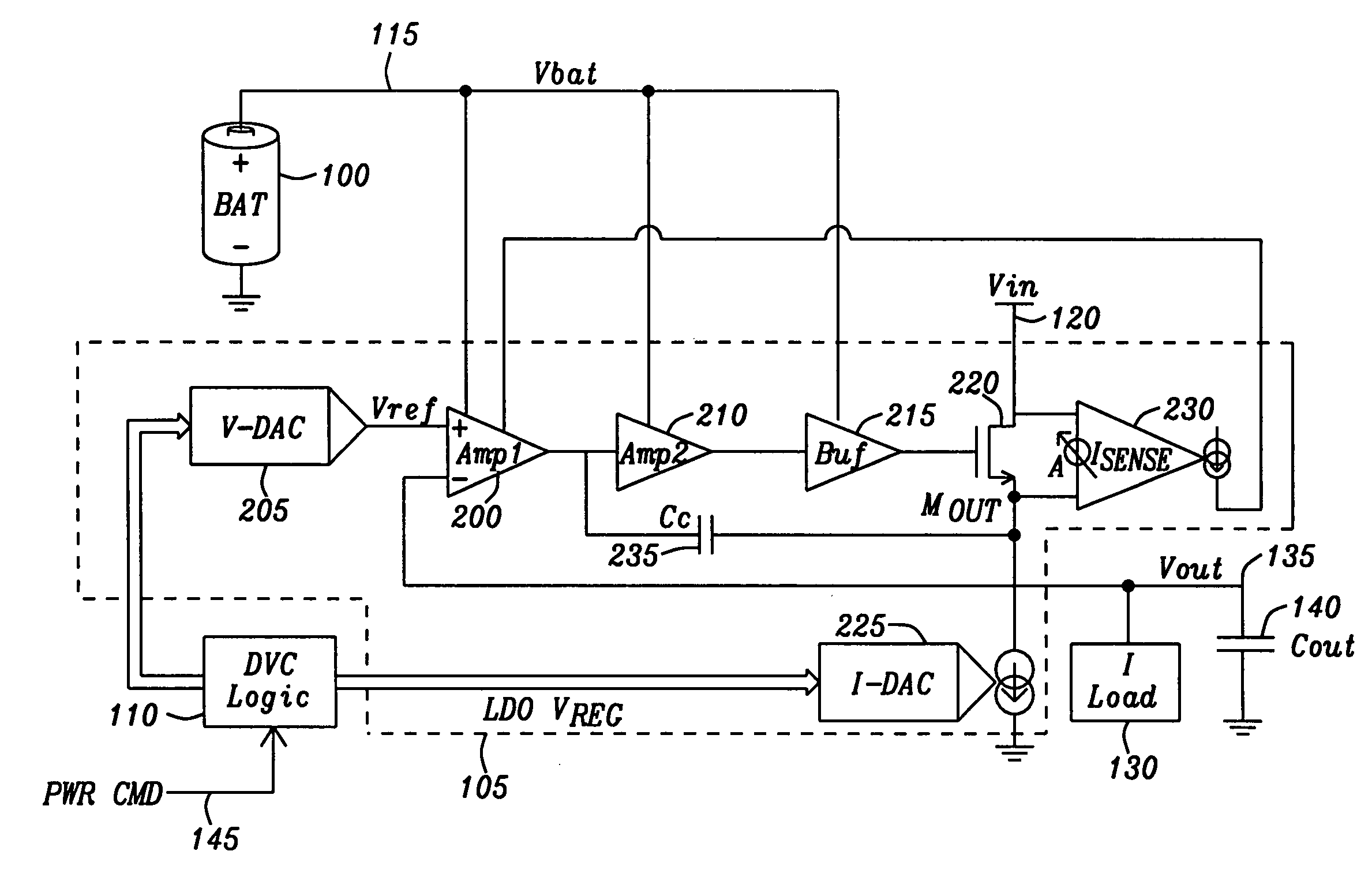
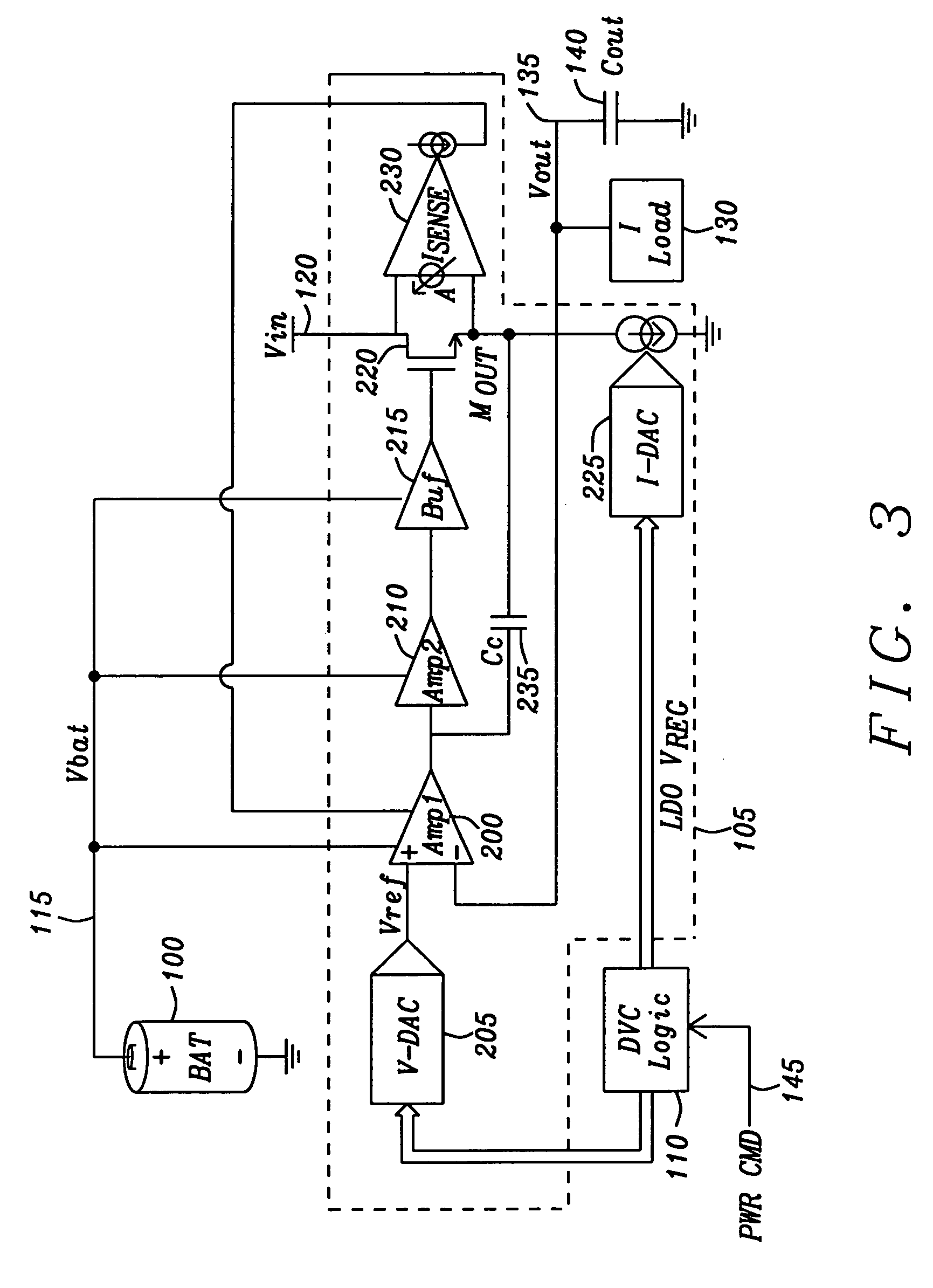
[0010]An object of this invention is to provide a low dropout voltage regulator circuit that minimizes the power consumption of the load circuit by dynamically adjusting its output voltage.

Problems solved by technology

Buck regulators are generally power efficient but can consume a significant area and need bulky external components (inductors).
However, for applications which require only a modest load current, the area penalty of a buck converter may be unacceptable.

Method used


Image

  • Low drop-out voltage regulator with dynamic voltage control
  • Low drop-out voltage regulator with dynamic voltage control
  • Low drop-out voltage regulator with dynamic voltage control

Examples


Embodiment Construction

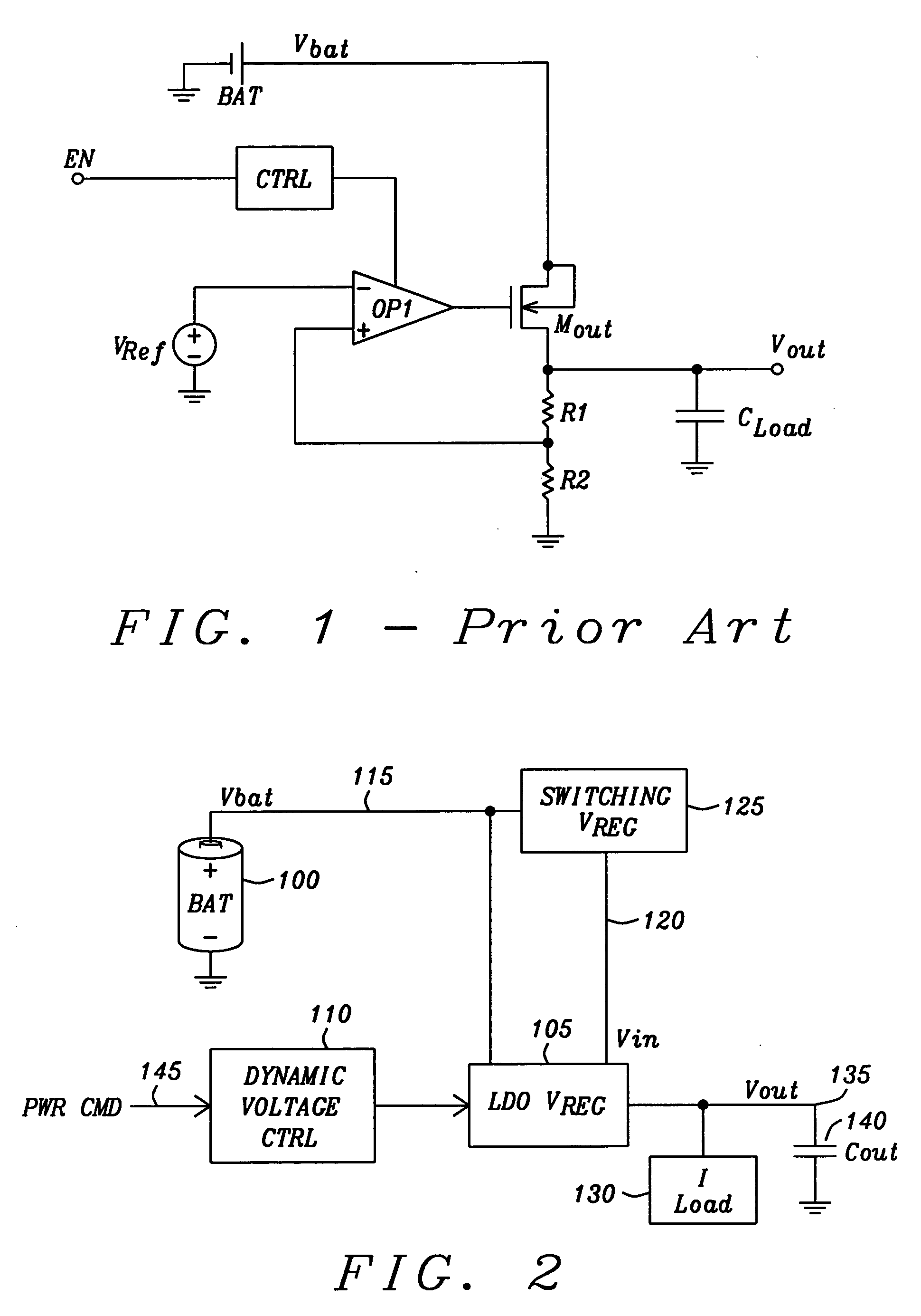
[0026]U.S. Pat. No. 6,856,124 (Dearn, et al.) describes a low dropout voltage regulator with wide output load range and fast internal loop. The circuit is internally compensated and uses a capacitor to ensure that the internal pole is more dominant than the output pole as in standard Miller compensation. The quiescent current is set to be proportional to the output load current. No explicit low power drive stage is required. The whole output range is covered by one output drive stage. This means the total consumption of quiescent or wasted current is reduced. An excellent power supply rejection ratio (PSRR) is achieved due to load dependent bias current. Dearn, et al. covers the basic low dropout voltage regulator architecture. However, the low dropout voltage regulator of Dearn, et al. is unable to dynamically change its output voltage.

[0027]What is needed is a low dropout voltage regulator circuit in which the output voltage can be dynamically increased or decreased in response to...


PUM


Abstract

A low dropout voltage regulator circuit that dynamically adjusts its output voltage has a voltage adjustment circuit in communication with a dynamic voltage controlling circuit for modifying the output voltage of the low dropout voltage regulator. A first amplification circuit is connected to receive an adjusted reference voltage from the voltage adjustment circuit and compare it with a feedback signal from the output voltage to provide a drive signal to a signal input terminal of a follower output transistor. An output terminal of the follower output transistor provides the output voltage of the regulation circuit. An adjustable internal load circuit applies a load current to the output terminal of the follower output transistor to increase the bandwidth of the output of the voltage regulation circuit that is sensed by a dynamic biasing sensing circuit to generate a dynamic biasing signal that modifies the bandwidth of the first amplification circuit.

Description

RELATED PATENT APPLICATIONS[0001]U.S. patent application Ser. No. 10 / 191,491, filed on Jul. 9, 2002, issued as U.S. Pat. No. 6,856,124 (Dearn, et al.), Feb. 15, 2005, assigned to the same assignee as the present invention, and incorporated herein by reference in its entirety.BACKGROUND OF THE INVENTION[0002]1. Field of the Invention[0003]This invention relates generally to voltage regulator circuits. More particularly, this invention relates to low dropout voltage regulator circuits. Even more particularly this invention relates to low dropout voltage regulator circuits having dynamic voltage control.[0004]2. Description of Related Art[0005]Battery powered applications such as smart-phones and tablet computers demand long battery life and therefore highly power efficient circuits. Often, the power supply voltage of digital circuits for the battery power applications must be adjusted during operation to minimize power consumption, since the power dissipated is proportional to the squ...

Claims


Application Information

Patent Timeline
IPC IPC(8): G05F1/10
CPCG05F1/575
Inventor HOWES, RUPERTTAVARES, ALEXANDRECLOWES, ANTHONYCHILDS, MARK
Owner DIALOG SEMICONDUCTOR GMBH
Learn More