Beam forming device and method

Active Publication Date: 2012-11-29
SONY CORP
View PDF36 Cites 53 Cited by
  • Summary
  • Abstract
  • Description
  • Claims
  • Application Information

AI Technical Summary

Benefits of technology

[0015]It is an object of the present disclosure to provide a beam forming device and a corresponding method that can be used for active imaging in the near field and provide a high accuracy even if the distance of the scene, e.g. of an object to be imaged, changes. It is a further object of the present disclosu

Problems solved by technology

However, this system operates in scenarios where there is a larg

Method used


Image

  • Beam forming device and method
  • Beam forming device and method
  • Beam forming device and method

Examples


Embodiment Construction

[0048]Active imaging systems, including active imaging devices and methods, are becoming increasingly popular at ultrasonic, microwave, millimetre and terahertz frequencies for a number of applications including medical and security applications. Security active imaging systems for example enable suspicious items hidden under clothes or in bags to be visualised and to be easily identified. Medical active imaging systems on the other hand enable the visualisation of a huge variety of biological items.

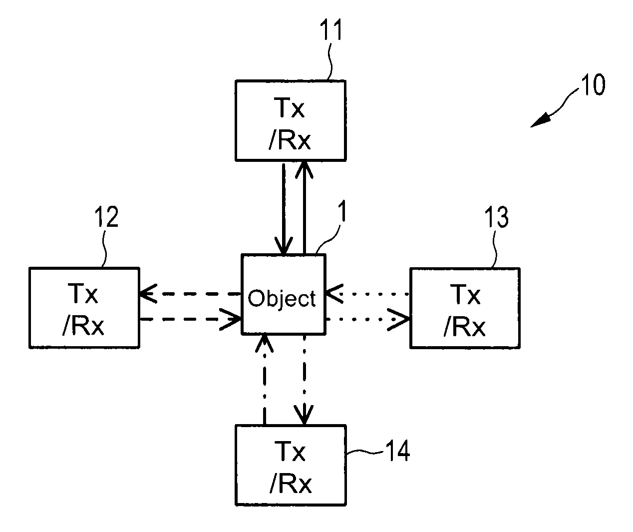
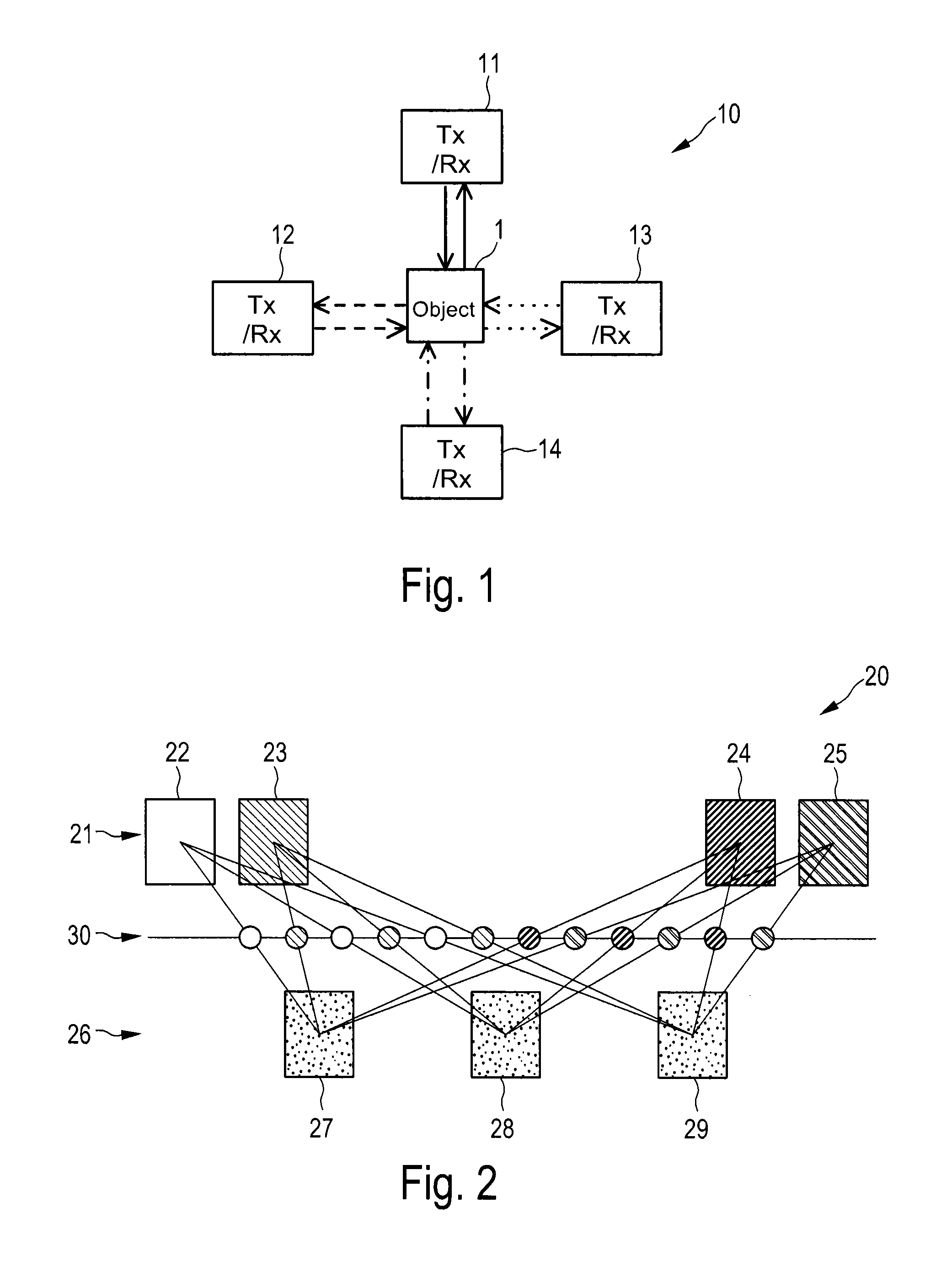
[0049]The arrangement of transmitter and receiver in an active imaging system may take on many different forms but in the following systems in which multiple transmitters and receivers work together to form a MIMO radar or MIMO active imaging device will be mainly considered.

[0050]There are predominately two different types of MIMO radar. The first type is called statistical MIMO. In this system the antennas are placed far apart from each other and typically consist of multiple radars to...


PUM


Abstract

The present disclosure relates to a beam forming device, comprising a transmit unit comprising at least two transmit elements that transmit radiation towards a scene, a receiver unit comprising at least two receive elements that receive radiation from said scene and that generate receive signals from said received radiation, and a beam forming unit that performs beam forming to obtain beam formed output signals from said receive signals by use of beam forming weights, wherein said beam forming weights are adapted to a distance between the scene and one or more transmit elements and/or receive elements, said distance being indicated by a distance indicator, and wherein said beam forming weights are changed if said distance changes.

Description

CROSS REFERENCE TO RELATED APPLICATION[0001]The present application claims the benefit of the earlier filing date of 11 167 065.9 filed in the European Patent Office on May 23, 2011, the entire content of which application is incorporated herein by reference.BACKGROUND[0002]1. Field of the Disclosure[0003]The present disclosure relates to a beam forming device and a corresponding method. The present disclosure relates further to an active imaging device and an active imaging method for imaging a scene as well as to a beam forming unit and a processing method. Still further, the present disclosure relates to a computer program and to a computer readable non-transitory medium storing such a computer program. The present disclosure relates particularly to MIMO beam forming devices and methods.[0004]2. Description of Related Art[0005]Active imaging systems are becoming more and more popular at ultrasonic, microwave, millimetre and terahertz frequencies for a number of applications inclu...

Claims


Application Information

Patent Timeline
IPC IPC(8): H01Q3/00
CPCH01Q3/2605G01S13/89G01S13/003G01S13/06G01S13/42G01S13/885G01S13/887G01S13/888H01Q3/24H01Q3/26H01Q3/34
Inventor STIRLING-GALLACHER, RICHARDWANG, QIBOEHNKE, RALF
Owner SONY CORP
Why Eureka
Try Eureka