Lighting Device and Projection-Type Display Apparatus Including Lighting Device

Active Publication Date: 2012-11-29
PANASONIC INTELLECTUAL PROPERTY MANAGEMENT CO LTD
View PDF6 Cites 82 Cited by
  • Summary
  • Abstract
  • Description
  • Claims
  • Application Information

AI Technical Summary

Benefits of technology

[0027]With this feature of the present invention, an optical axis to be obtained can easily be synthesized. This allows for synthesis of, for example, white light of high intensity.
[0028]In addition, if the first solid-state light source, the second solid-state light source, and the third solid-state light source are each a semiconductor laser that emits blue light, and the first fluorescence is green and the second fluorescence is red, it is possible to efficiently obtain white light by using blue light as projection light and combining the blue light with the green fluorescence and the red fluorescence. Unlike in a case where blue fluorescence is used, since projection light is used for blue color, the loss due to conversion does no

Problems solved by technology

However, the excitation light, which is irradiated onto phosphors of red, green, and blue, cannot be changed for each phosphor.
Therefore, in the proposed device, most suitable excitation light cannot be selected for each phosphor, which causes a problem of insufficient brightness of the fluorescence.
A

Method used


Image

  • Lighting Device and Projection-Type Display Apparatus Including Lighting Device
  • Lighting Device and Projection-Type Display Apparatus Including Lighting Device
  • Lighting Device and Projection-Type Display Apparatus Including Lighting Device

Examples


first embodiment

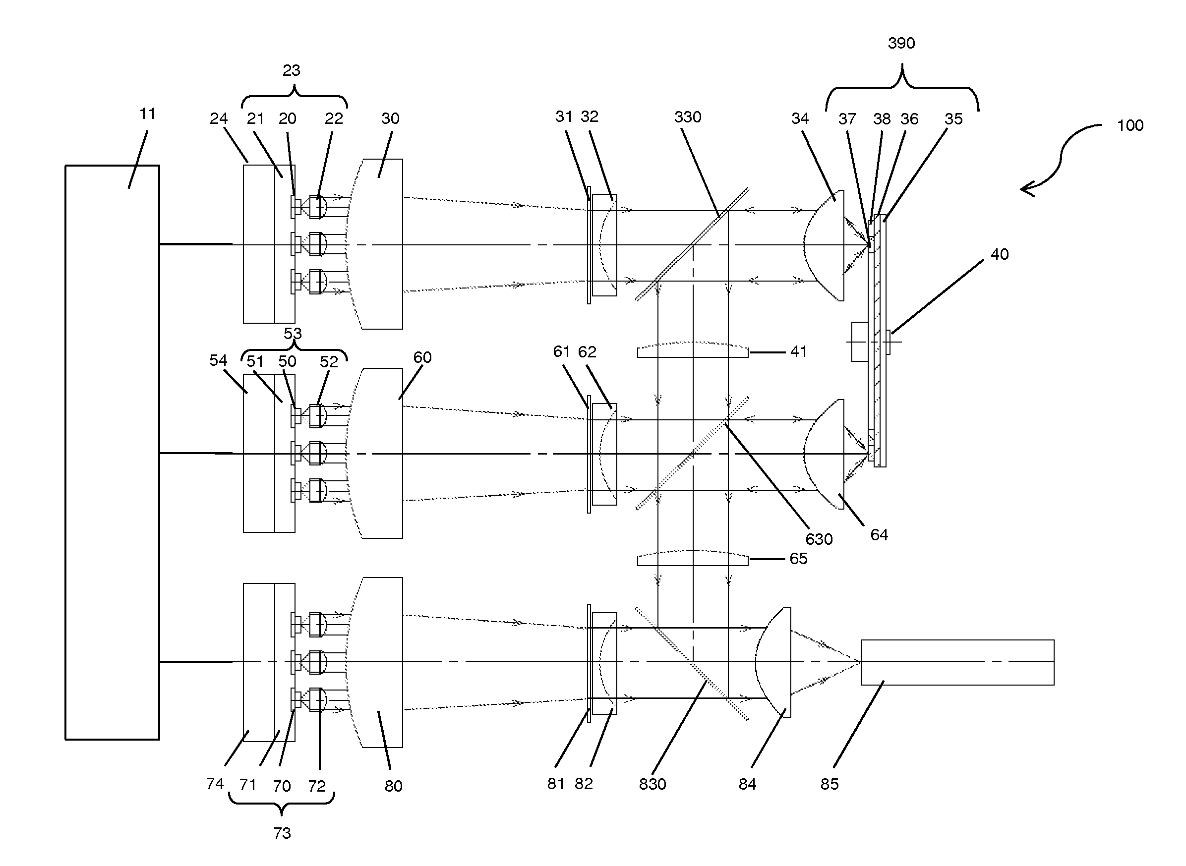
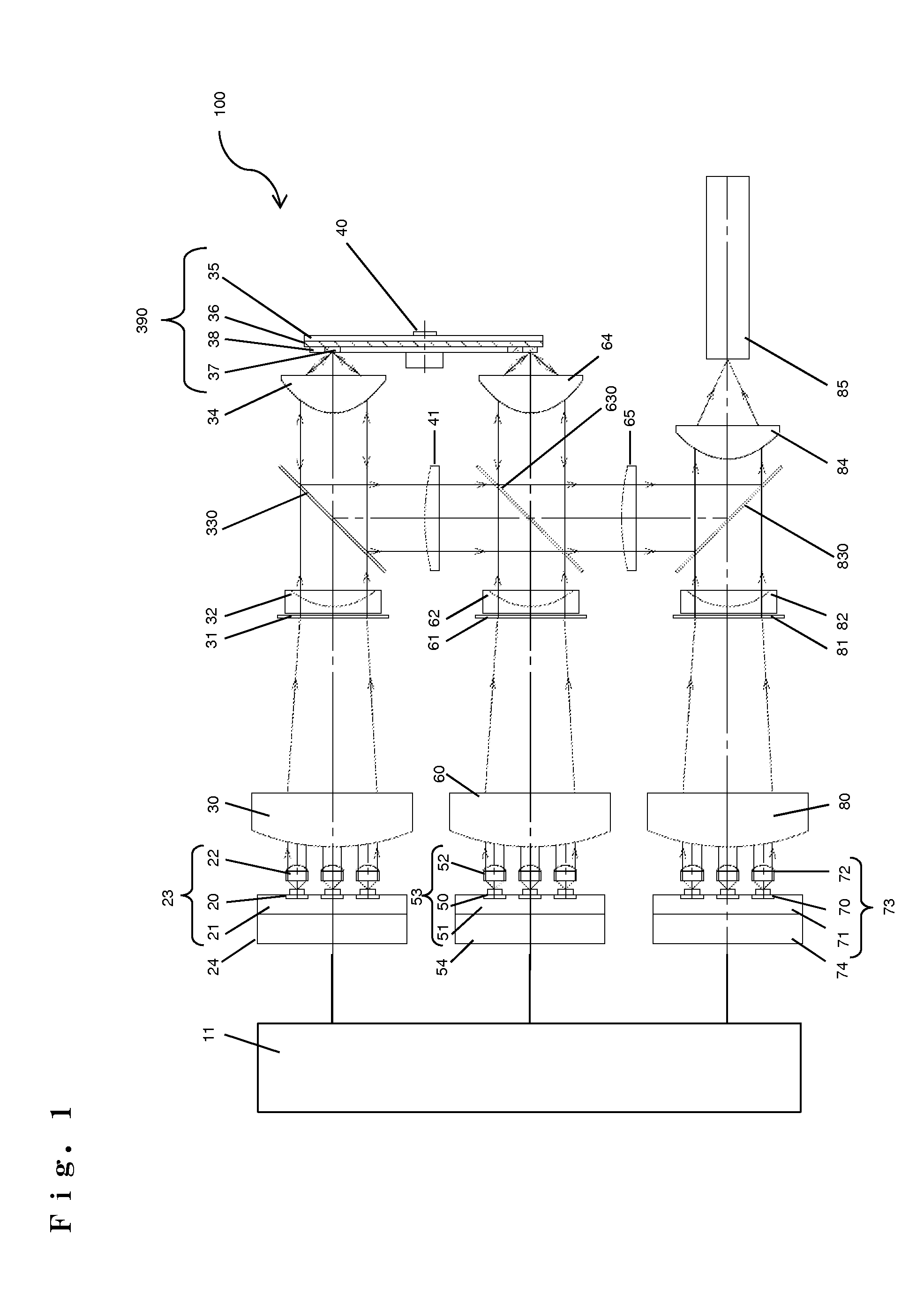
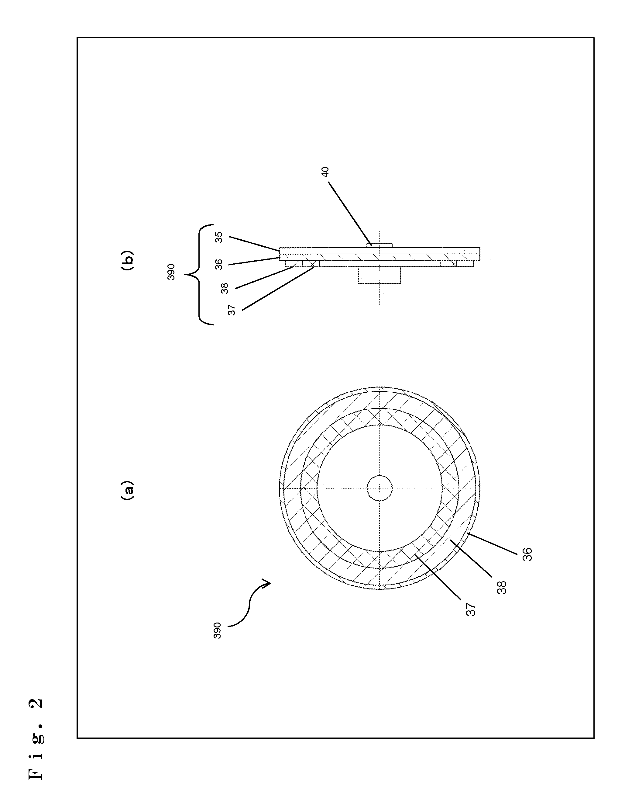
[0045]FIG. 1 is a diagram showing the configuration of a lighting device 100 according to a first embodiment of the present invention. FIG. 2 is a diagram illustrating a phosphor substrate 390 used for the lighting device 100 shown in FIG. 1, and (a) is a plan view, and (b) is a side view. FIG. 3 is a diagram illustrating solid-state light sources 20, 50, and 70 used for the lighting device 100 shown in FIG. 1. FIG. 4A is a diagram showing the spectral characteristics of a dichroic mirror 330 used for the lighting device 100 shown in FIG. 1. FIG. 4B is a diagram showing the spectral characteristics of a dichroic mirror 630 used for the lighting device 100 shown in FIG. 1.

[0046]As shown in FIG. 1, the lighting device 100 according to the first embodiment includes: a first solid-state light source 20; a second solid-state light source 50; a third solid-state light source 70; plates 21, 51, and 71 that hold the solid-state light sources 20, 50, and 70, respectively; cooling devices 24,...

second embodiment

[0071]FIG. 5 is a diagram showing the configuration of a lighting device 101 according to a second embodiment of the present invention. FIG. 6 is a diagram illustrating a phosphor substrate 391 used for the lighting device 101 shown in FIG. 5, and (a) is a front view, (b) is a side view, and (c) is a back side view.

[0072]As shown in FIG. 5, the configuration of the lighting device 101 according to the second embodiment is the same as that of the lighting device 100 according to the first embodiment except that the third emission light emitted from the third solid-state light source 70 acts as excitation light, and a third phosphor 39 applied onto the phosphor substrate 391 emits third fluorescence. Hereinafter, the common components are denoted by the same reference characters, detailed description thereof is omitted, and the lighting device 101 according to the second embodiment will be described focusing on the difference from the first embodiment.

[0073]

[0074]The second embodiment...

third embodiment

[0087]FIG. 7 is a diagram showing the configuration of a lighting device 102 according to a third embodiment of the present invention.

[0088]As shown in FIG. 7, the configuration of the lighting device 102 according to the third embodiment is the same as that of the lighting device 100 according to the first embodiment except that two phosphor substrates, that is, a phosphor substrate 392 onto which the first phosphor 37 is applied, and a phosphor substrate 393 onto which the second phosphor 38 is applied, are used. Hereinafter, the common components are denoted by the same reference characters, detailed description thereof is omitted, and the lighting device 102 according to the third embodiment will be described focusing on the difference from the first embodiment.

[0089]

[0090]In the third embodiment, two phosphor substrates, the phosphor substrate 392 and the phosphor substrate 393, are used. These phosphor substrates are circular similar to the phosphor substrate 390 according to ...


PUM


Abstract

A lighting device configured to output light of predetermined color includes: a plurality of solid-state light sources including at least a first solid-state light source and a second solid-state light source; a drive section configured to drive each of the plurality of solid-state light sources individually; a first phosphor for excitation by first emission light emitted from the first solid-state light source; and a second phosphor for excitation by second emission light emitted from the second solid-state light source, and first fluorescence and second fluorescence are of different color.

Description

BACKGROUND OF THE INVENTION[0001]1. Field of the Invention[0002]The present invention relates to lighting devices and projection-type display apparatuses including a lighting device, and more particularly relates to a lighting device furnished with a plurality of light sources and capable of changing the lighting timing and the intensity of each light source individually, and to a projection-type display apparatus including the lighting device.[0003]2. Description of the Background Art[0004]Lighting devices including a light source are incorporated in, for example, projectors that concentrate light emitted from the light source onto a display element called a DMD (digital micromirror device) or onto a liquid crystal panel and thereby display a color image (color video image) on a screen. Most such lighting devices incorporated in projectors or the like have used discharge lamps with high brightness as their light sources. In recent years, however, many devices that use LEDs (light e...

Claims


Application Information

Patent Timeline
IPC IPC(8): G03B21/14H05B37/02
CPCH04N9/3111H04N9/3161G03B33/12G03B21/2013G03B21/204H04N9/3164
Inventor SUGIYAMA, HIROKIKITANO, HIROSHIYAMAGISHI, SHIGEKAZU
Owner PANASONIC INTELLECTUAL PROPERTY MANAGEMENT CO LTD
Why Eureka
Try Eureka