

Electrode material, paste, electrode plate, and lithium ion battery
- Summary
- Abstract
- Description
- Claims
- Application Information
AI Technical Summary
Benefits of technology
Problems solved by technology
Method used
Image

Examples
example 2
[0178]A dry material of Example 2 was obtained by the same manner as in Example 1 except that raw materials were mixed such that the molar ratio of Fe to LiMnPO4 (Fe / LiMnPO4) should be 0.031 instead of 0.053.
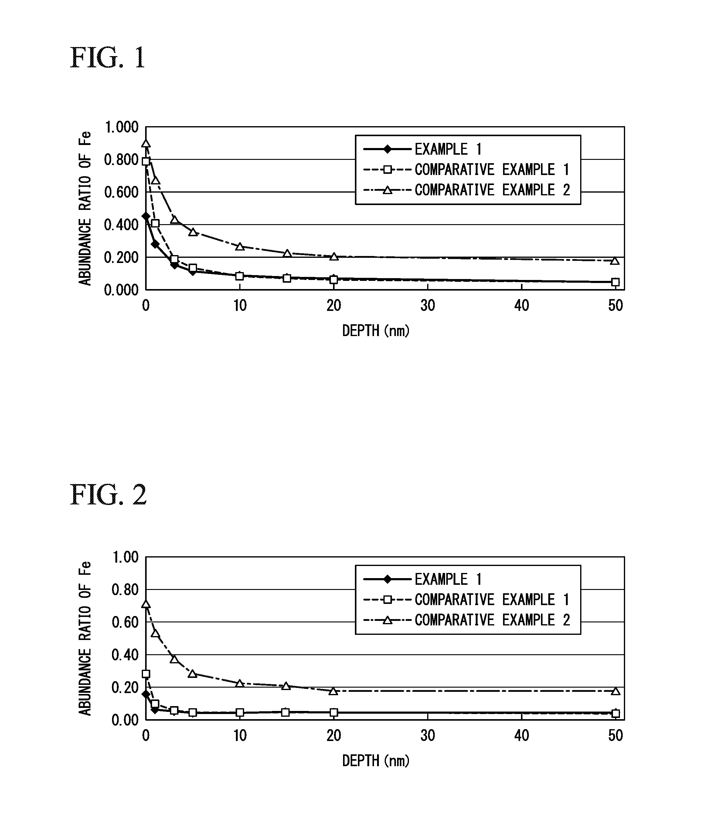
The abundance ratio of Fe in the resultant dry material was evaluated by the same method as in Example 1, and the result is shown in Table 1. In addition, the relationship between the depth and the abundance ratio of Fe is illustrated in FIG. 1.
The resultant dry material was baked in the same manner as in Example 1 to obtain an electrode material of Example 2. The result of the abundance ratio of Fe which was evaluated with respect to the resultant electrode material by the same manner as in Example 1 is shown in Table 1. In addition, the relationship between the depth and the abundance ratio of Fe is illustrated in FIG. 2.
Each of a paste, an electrode plate, and lithium ion battery of Example 2 was obtained by the same manner as in Example 1 except that the electrode material o...
example 3
[0179]A dry material of Example 3 was obtained by the same manner as in Example 1 except that raw materials were mixed such that the molar ratio of Fe to LiMnPO4 (Fe / LiMnPO4) should be 0.10. The abundance ratio of Fe in the resultant dry material was evaluated by the same method as in Example 1, and the result is shown in Table 1. In addition, the relationship between the depth and the abundance ratio of Fe is illustrated in FIG. 1.
The resultant dry material was baked in the same manner as in Example 1 to obtain an electrode material of Example 3. With respect to the resultant electrode material, the result of the abundance ratio of Fe which was evaluated by the same manner as in Example 1 is shown in Table 1. In addition, the relationship between the depth and the abundance ratio of Fe is illustrated in FIG. 2.
Each of a paste, an electrode plate, and lithium ion battery of Example 3 was obtained by the same manner as in Example 1 except that the electrode material obtained in Examp...
example 1
COMPARATIVE EXAMPLE 1
COMPARATIVE EXAMPLE 2
DEPTH
[FIG. 2]
ABUNDANCE RATIO OF Fe
PUM
 Abstract
Description
Claims
Application Information