
Device for determining the volume fraction of at least one component of a multi-phase medium

Inactive Publication Date: 2012-11-29
KROHNE MESSTECHNICK GMBH & CO KG
View PDF7 Cites 5 Cited by
  • Summary
  • Abstract
  • Description
  • Claims
  • Application Information

AI Technical Summary

Benefits of technology

[0012]A primary object of the present invention is to provide a device for determining the volume fraction of at least one component of a multi-phase medium and a method for operating such a device that makes the determination of the running time of the desired signal within the medium possible with increased accuracy and comparably low technical complexity.
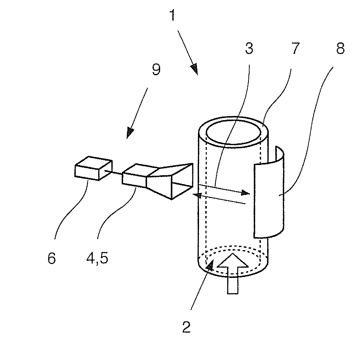
[0019]A further preferred design of the invention differs from the above-mentioned designs in that the polarization device is not a passive device, but rather is designed as an active polarization device, the emitting device emits the desired signal polarized in a first direction, the active polarization device turns and emits the desired signal in a second direction and the receiving device receives the desired signal polarized in the second direction and the evaluating device vectorially evaluates the received complete signal so that the desired signal polarized in the second direction can be differentiated from other parts of the received complete signal, in particular, from interference signals. In this design, the desired signal of interest is also characterized by polarization and is made differentiable from interference radiation not having this polarization. Furthermore, the volume filled with the multi-phase medium is passed through twice, so that a double length as opposed to the one-way transmission measurement is made available and, thus, the relative measuring error is smaller. Vectorial evaluation of the received complete signal—as described above—means that the received signal is evaluated according to amount and phase, so that different polarized parts can be differentiated from one another.
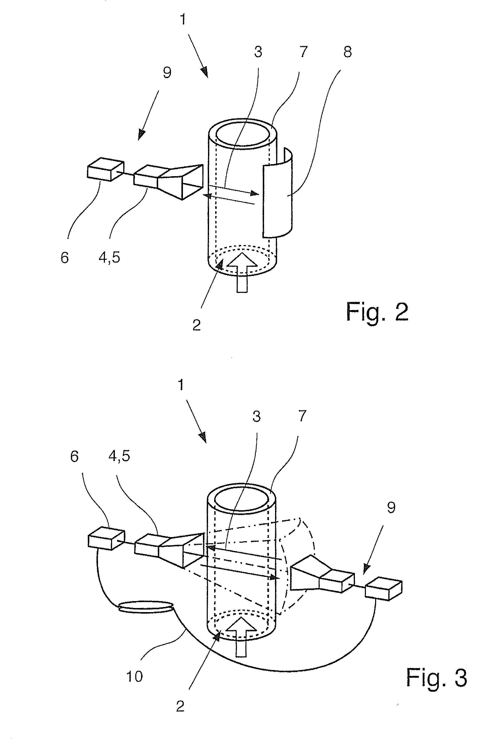
[0021]The device is then further designed so that the second, active polarization device turns the desired signal and emits it, in turn, through the medium and the first, passive polarization device turns this desired signal, in turn, in the first polarization orientation and further emits it through the medium, whereupon the receiving device receives the desired signal and the evaluating device vectorially evaluates the received complete signal so that the desired signal polarized in the second direction can be differentiated from other parts of the received complete signal. In a concrete example, it is also possible that the emitting device emits a vertically polarized desired signal that is turned 90° by the first, passive polarization device, thus, is practically not able to be received by the receiving device; the second, active polarization device then turns the desired signal, for example, 180°—reflection factor 1—, the signal is then emitted to the first, passive polarization device and turned another 90° there and is thus receivable again for the receiving device. In such an arrangement, the desired signal passes through the volume containing the medium four times, which leads to a corresponding reduction of the measuring error. The advantage of characterizing the desired signal of interest as opposed to the interference signal, which is not of interest and is to be suppressed, is further achieved in this manner.
[0023]In the method according to the invention a polarization influence is set during a first measurement by the active polarization device and a first received signal is detected by the receiving device. Then, a second polarization influence different than the first polarization influence is set during a second measurement by the active polarization device and a second received signal is detected. According to this, there are two received signals with differently polarized desired signals. Then, the first received signal and the second received signal are superimposed in such a manner that interference signals contained in the first received signal and the second received signal are nullified, in particular desired signals contained in the first received signal and in the second received signals are added together. This can be easily imagined, for example, in a first measurement, in which the active polarization device is deactivated, i.e., the first polarization influencing is implemented as a non-influencing factor, wherein the active polarization device is set in the second measurement in which a negative reflection factor is implemented, i.e., a phase shift of the desired signal of 180° is implemented. When the part of the received complete signal that shows this phase shift, which therefore comes from the desired signal of interest, is associated with a negative sign and the first received signal and the second received signal influenced in this manner are subsequently subtracted from one another, the interference signals contained in the received signals are practically nullified—provided that they have the same structure, because they come from solid reflection surfaces—while desired signals having different signs are added together, which simplifies the recognition of the desired signal overall, and thus, the determination of the signal running time.

Problems solved by technology

Interesting information about the transmission behavior of the space filled with the multi-phase medium can be obtained using a network analyzer in a laboratory construction; however, this solution is complex in terms of equipment and thus also expensive.
Furthermore, there is the problem that desired signal emitted from the sending device into the multi-phase medium does not arrive at the receiving device in a direct manner through the medium, but rather interference signals are received, which result, for example, from reflections on the walls of a container holding the multi-phase medium or a tube, so that the recognition of the actual desired signal of interest is difficult with the received overall signal.

Method used


Image

  • Device for determining the volume fraction of at least one component of a multi-phase medium
  • Device for determining the volume fraction of at least one component of a multi-phase medium
  • Device for determining the volume fraction of at least one component of a multi-phase medium

Examples


Embodiment Construction

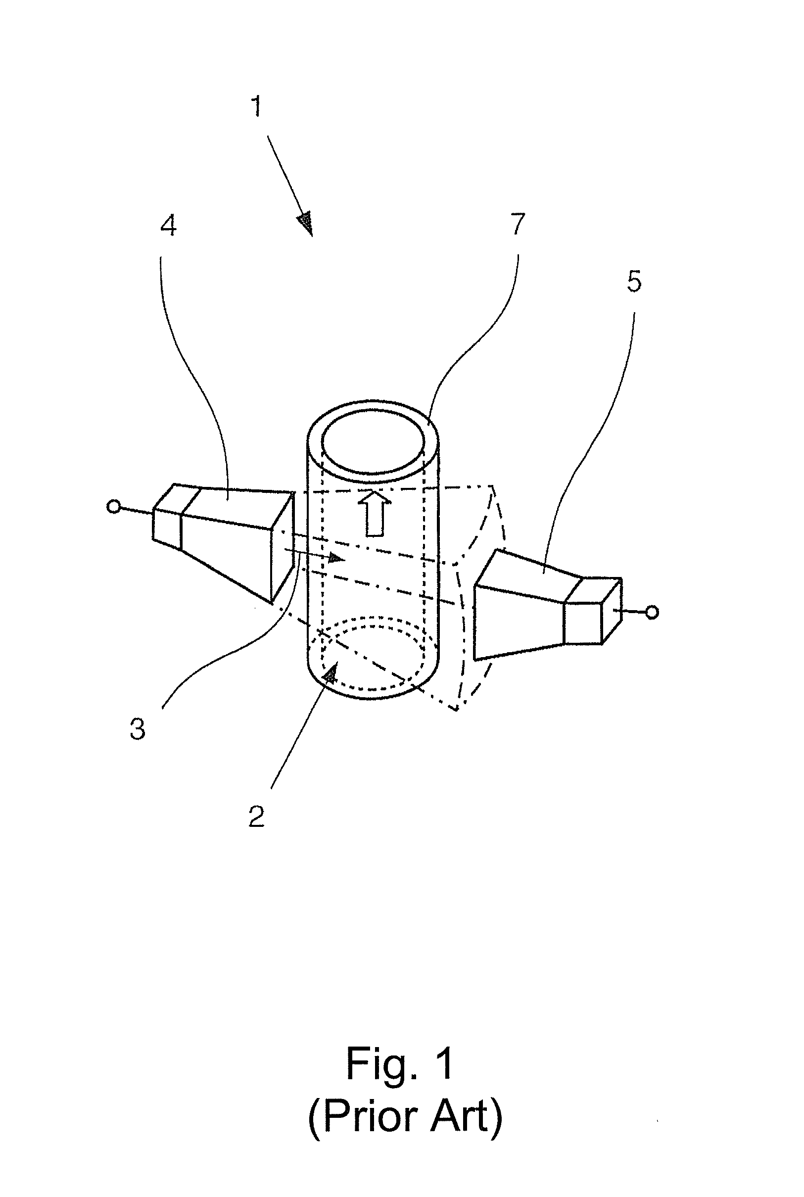
[0031]A device 1 is shown in FIG. 1 for determining the volume fraction of at least one component of a multi-phase medium 2 on the basis of the running time of an electromagnetic desired signal 3 emitted in the multi-phase medium 2, having an emitting device 4 for emitting the desired signal 3 into the multi-phase medium 2, having a receiving device 5 for receiving the desired signal 3 and having an evaluating device, not shown here, and identified with the reference number 6 in other figures for determining the running time of the desired signal 3 between the emitting device 4 and the receiving device 5.

[0032]In the present case, the multi-phase medium 2 is lead in a tube 7, wherein the medium 2 moves in the direction given by the arrow. In the prior art, the desired signal 3 emitted by the emitting device 4 and the desired signal 3 received by the receiving device 5 are lead to a network analyzer via high frequency lines, from which conclusions can be drawn about the transmission ...


PUM


Abstract

A device for determining the volume fraction of at least one component of a multi-phase medium on the basis of the running time of an electromagnetic desired signal emitted in the multi-phase medium, having at least one emitting device for emitting the desired signal into the multi-phase medium, having at least one receiving device for receiving the desired signal, and having an evaluation device for determining the running time of the desired signal between the emitting device and the receiving device, and at least one polarization device arranged between the emitting device and the receiving device. The desired signal is emitted at least indirectly from the emitting device through the multi-phase medium to the polarization device, the polarization device influences the polarization of the desired signal and the polarization-influenced desired signal is emitted at least indirectly from the polarization device to the receiving device which receives it.

Description

BACKGROUND OF THE INVENTION[0001]1. Field of the Invention[0002]The invention relates to a device for determining the volume fraction of at least one component of a multi-phase medium on the basis of the running time of an electromagnetic desired signal emitted in the multi-phase medium, having at least one emitting device for emitting the desired signal into the multi-phase medium, having at least one receiving device for receiving the desired signal, and having an evaluation device for determining the running time of the desired signal between the emitting device and the receiving device. Furthermore, the invention relates to a method for operating such a device for determining the volume of at least one component of a multi-phase medium.[0003]2. Description of Related Art[0004]The volume fraction of a component of a multi-phase medium consisting of multiple components can be of interest in technical processes for many different reasons. For example, in the conveying of multi-phas...

Claims


Application Information

Patent Timeline
IPC IPC(8): G01J4/00
CPCG01N33/222G01N22/00
Inventor BAER, CHRISTOPH
Owner KROHNE MESSTECHNICK GMBH & CO KG
Learn More