Luminaire Assembly

a technology of assembly and light source, applied in the field of light source, can solve the problems of reducing service life, increasing the complexity of the device design, and requiring more energy, and achieve the effects of increasing the operating voltage, improving light performance, and increasing the light emission

Inactive Publication Date: 2012-11-29
OSRAM GMBH
View PDF8 Cites 0 Cited by
  • Summary
  • Abstract
  • Description
  • Claims
  • Application Information

AI Technical Summary

Benefits of technology

[0012]A considerable service life extension of the luminaire assembly is made possible if at least one of the lighting functions takes place at an operating voltage of the light source reduced by about 5 to 10% compared with the standard operating voltage. An increase in the operating voltage for at least one lighting function by 5 to 10% compared with the standard operating voltage makes possible an improved light performance as a result of the increase in the light emission.

Problems solved by technology

The higher luminous flux can for example be achieved by means of a more powerful halogen lamp, which is however more complex technically in terms of its device design in comparison with a less powerful halogen lamp and requires more energy.
Alternatively, it is also possible to employ a conventional halogen lamp with an increased output, which disadvantageously results in a reduced service life.

Method used


Image

  • Luminaire Assembly
  • Luminaire Assembly

Examples


Embodiment Construction

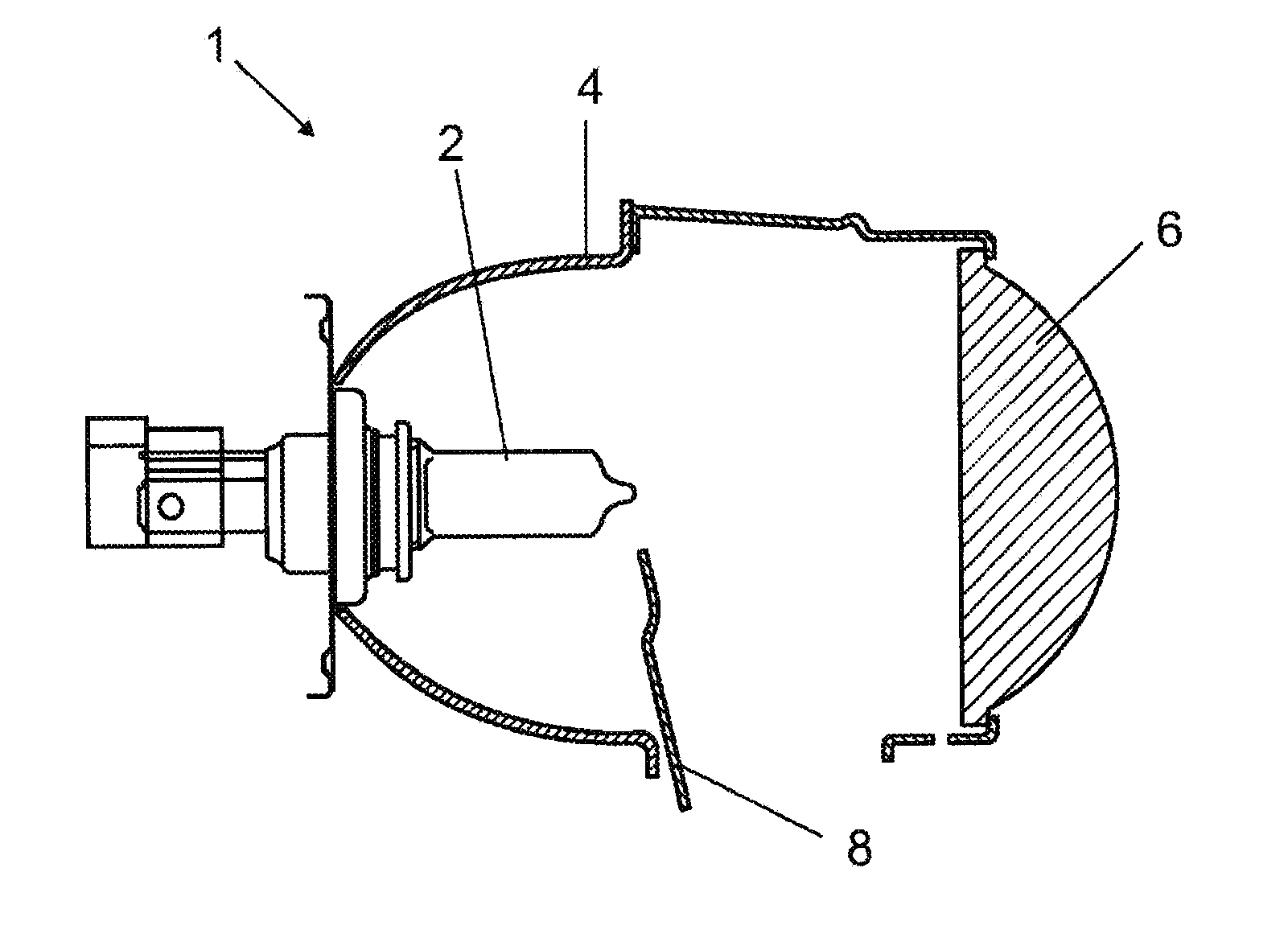
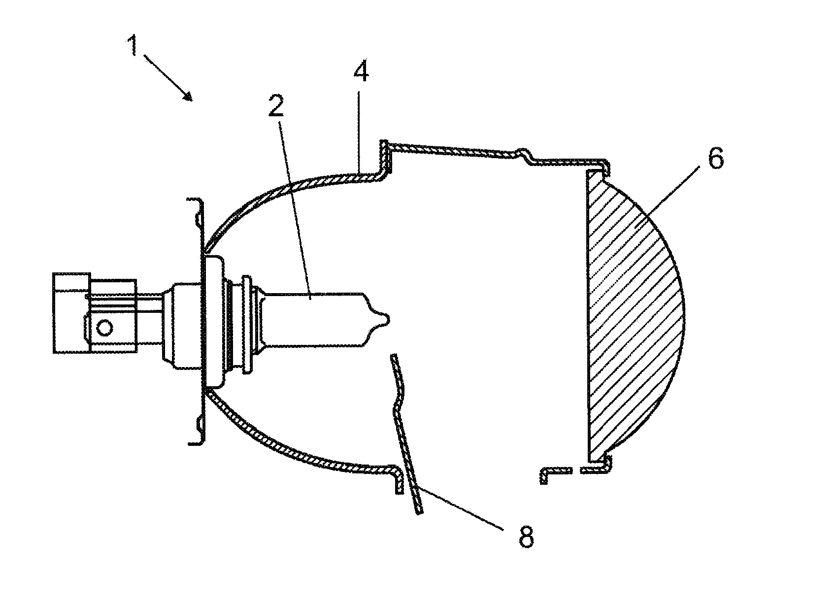
[0019]The single FIGURE shows a greatly simplified schematic illustration of a luminaire assembly 1 in accordance with an exemplary embodiment. Here this is a bi-halogen headlight for a motor vehicle. Such headlights produce a dipped beam and a main beam from a single light source. The light source illustrated in this FIGURE is an H7 tungsten halogen bulb, which is referred to in the following as lamp 2. The H7 tungsten halogen bulb has only one filament which serves as the light source for producing the main beam and also the dipped beam.

[0020]The luminaire assembly 1 has a reflector 4 encompassing the lamp 2 and a projection lens 6 lying in a beam path.

[0021]It is possible to switch between the dipped beam and main beam lighting functions by means of a baffle 8 arranged between the projection lens 6 and the lamp 2. The dipped beam and main beam lighting functions thus differ in that a cross-section of the beam path is greater for the main beam than for the dipped beam. The baffle ...


PUM


Abstract

A luminaire assembly, in particular a bi-halogen headlight for a motor vehicle, having at least one light source, which has at least two lighting functions, characterized in that the light source has a different operating voltage in each case with regard to the at least two lighting functions.

Description

AREA OF TECHNOLOGY[0001]The invention is based on a luminaire assembly in accordance with the preamble of claim 1.PRIOR ART[0002]Document DE 10 2006 057 748 A1 discloses such a luminaire assembly which is employed for a motor vehicle headlight. Here this is a bi-halogen headlight by means of which a dipped beam and a main beam are produced from a single light source. When the main beam of a motor vehicle is actuated, a baffle is moved by means of a magnetic force out of a beam path of the light source in order to release a greater area of the beam path. Conversely, on switching from the main beam to the dipped beam, the baffle is moved into the beam path. On switching between main beam and dipped beam, the light color and light intensity remain essentially unchanged. An H7 or H9 halogen lamp for example is employed as the light source for such a bi-halogen headlight. Alternatively, a xenon lamp can be used as the light source.[0003]On dipped beam, such motor vehicle headlights exhib...

Claims


Application Information

Patent Timeline
Patent Type & Authority Applications(United States)
IPC IPC(8): B60Q1/04
CPCB60Q1/1415F21S41/00B60Q1/08B60Q1/1438
Inventor HELBIG, PETERHERING, OLIVERKAPS, HARALDWITTMANN, KLAUS
Owner OSRAM GMBH
Why Eureka
Try Eureka